


Installation Guide
69-2285EFS—03 10
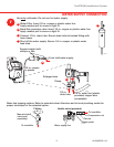
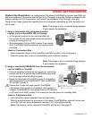
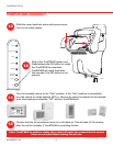
Optional Add-On Air Proving is a configuration that allows TrueSTEAM to double-check physi-
cal air movement.
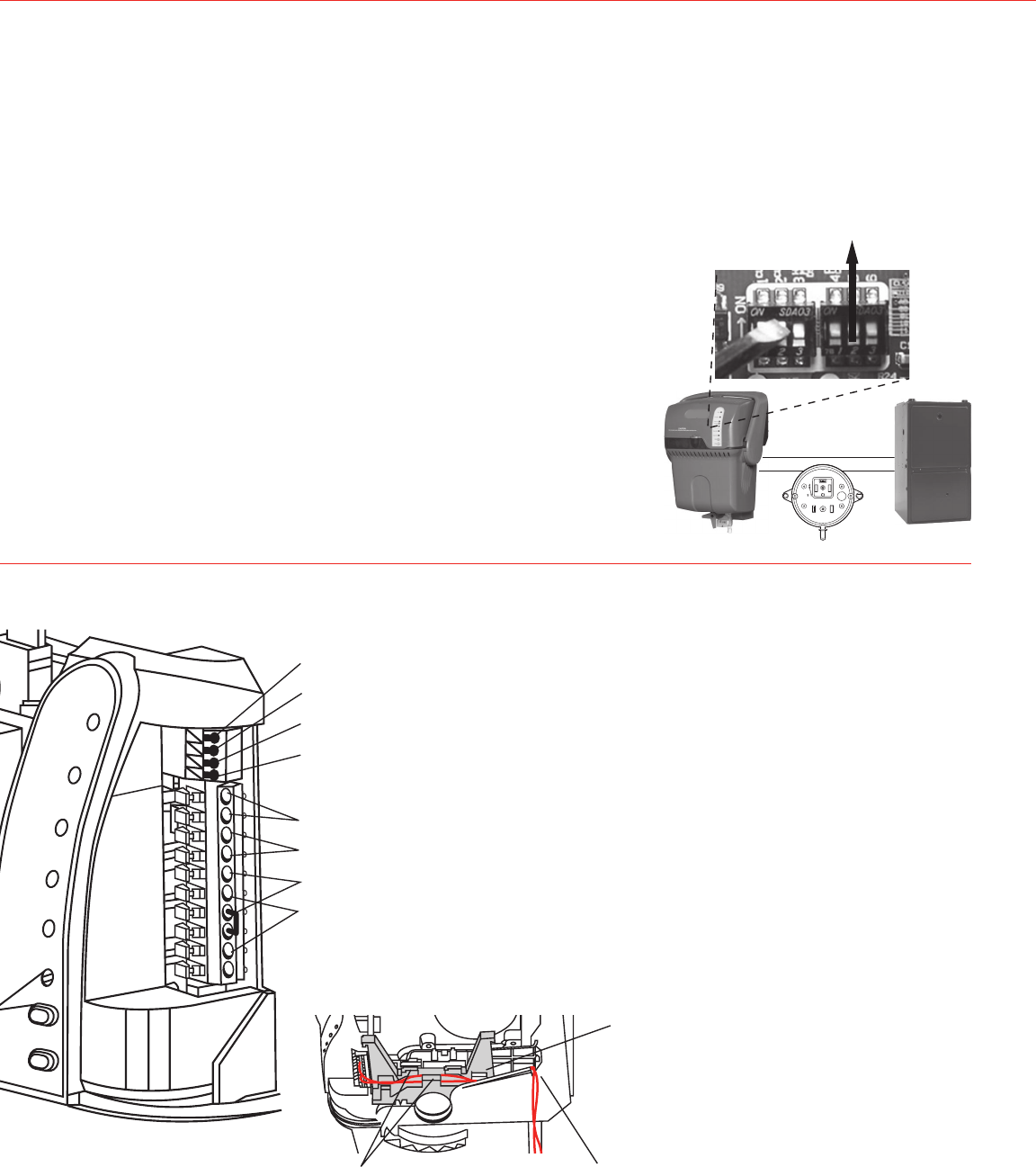
Air proving is configured through DIP 5 on TrueSTEAM. Set DIP 5 up with DIP 4 down to enable
air proving.
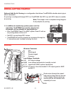
1. In addition to monitoring system power and fan
operation, TrueSTEAM can monitor physical air
movement via an external air proving device.
• WireTrueSTEAMRandCtoHVACsystemRandCwithan
air proving device in-line on C.
• SetDIP5upandkeepDIP4down.
• TrueSTEAMwilllookforphysicalairmovementthroughits
C connection prior to steam entering the duct.
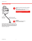
M24893
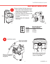
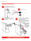
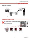
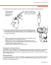
Route wires through the raised
tabs and out the notch at the rear
of the chassis. Ensure wires are
secure and do not interfere with
assembly of cover.
Tabs Notch
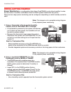
Wireless Terminals
A Hot
B Send signal
C Receive signal
D Common
Low-Voltage Terminals
24V AC output voltage
HUM Low-voltage terminals for humidity control.
C,R InputsfromHVACsystemtransformer.
GT,GF GTinputisfromthermostatG.GFoutputgoestoHVAC
system G.
M27732
24V
24V
HUM
HUM
C
GT
R
RT
GF
EXT
A
B
C
D
M28688
R
C
R
C
DIP 5
C
1
2
3
1
2
3
2
3
NC
NO
+
PI
ASSEMBLED
IN MEXICO
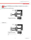
Note: This image is not a complete wiring diagram.
It only depicts air proving.
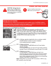
WIRING
WIRING–GETTING STARTED