


HA40 4-Channel Controller
Revision 1 (08/08)
HA40 Technical Manual 1-3
1�1 Data Display Screens
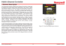
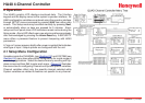
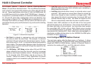
The HA40 Controller offers three modes for displaying monitored data,
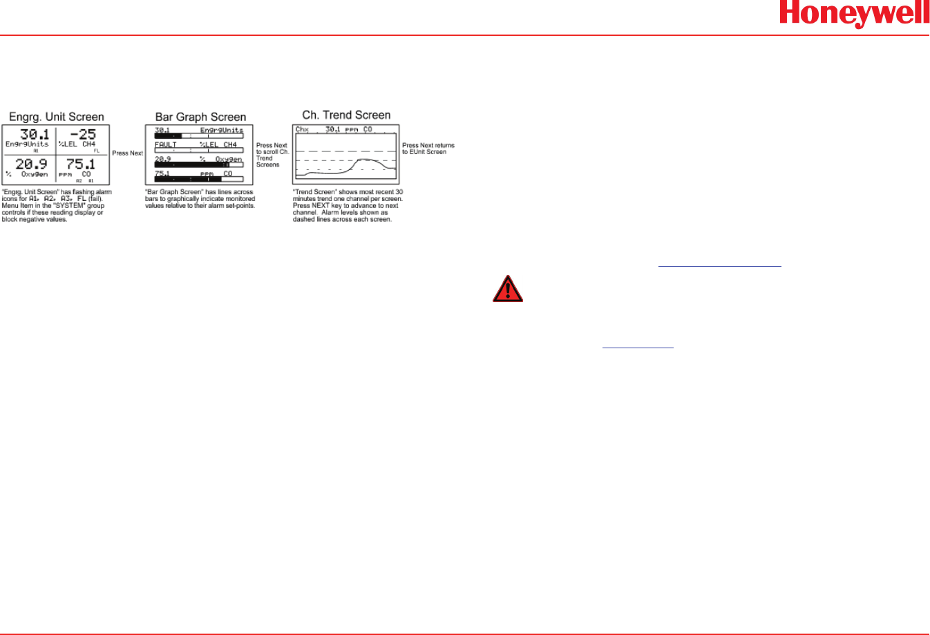
shown in Figure 1-4.
Figure 1-4. Data Display Screens
1�2�1 Engineering Unit Screen
The Engineering Unit screen shown in Figure 1-4 allows each channel’s
value and its 10-digit Eunits tag to be viewed simultaneously. A1, A2,
A3, FL icons at lower right of each reading ash if ALARM 1, 2, 3 or
FAULT alarms activate for this channel.
1�2�2 Bar Graph Screen
Values are displayed graphically as bar graphs with alarm levels
indicated by vertical dashed lines across each bar. The bar graph
screen is very useful for emphasizing current reading relative to the
channel’s alarm set-point. Live readings and their Eunits tag appear
above each bar graph.
1�2�3 Trend Screen
The HA40 also provides 30-minute trend screens for each channel as
shown in Figure 1-4. Live readings and their Eunits tag are displayed
across the top of each trend screen. Channel numbers are shown in
the upper right and are selected by the Next key. A1. A2 and A3 alarm
levels appear as horizontal dashed lines across the screen.
1�3 Specifications
1�3�1 Power Supply Requirements
The HA40 is equipped with an integral 15 watt universal AC input /
24 VDC output switching power supply. Standard HA40 AC power
requirements are 100-240 VAC 50/60 Hz @ .45 amp max (including
inrush) and 20 watts steady state, applied to TB5 on the motherboard. If
AC power is not available, the HA40 may also be powered with 24 VDC
applied to TB1 on the motherboard. A primary DC source or back-up
DC source capability should be determined by the total system power
budget calculation with guard-band included. A back-up DC power
source may also be connected to TB1 for automatic switchover if the
AC power source fails. See Figures 3-1 & 3-2 for wiring information.
Warning
A back-up or external DC power source DOES NOT source aux power
output (TB3 - see Figure 3.1)