


HA40 4-Channel Controller
Revision 1 (08/08)
HA40 Technical Manual 3-3
U2
J1
S1
TP1
S2
PS1
U3
CR5
2-AMP FUSE
(5 x 20mm)
U5
K2
K1
P3
J2 3BT2BT1BT
P1
P2
D2
D1
N/CN/O
C
RELAY 1
N/CN/O
C
RELAY 2
+
ALARM
-
RESET
DC PWR
+
SUPPLY
-
INPUT
+
OUTPUT
-
POWER
AUX
-
Common
(0-volts)
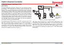
0010-1167 Rev C
2-Channel Controller
MotherBoard
1
RS-R85 / ETHERNET OPTION
1
Assy.10-0215
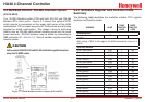
DATA-LOGGER PORT
DRY CONTACTS
DISCRETE RELAY OPTION
(See dwg. 10-0222)
Note: If installed, this option
blocks access to the fuse and
must be removed to replace fuse.
ALARM OPTION
1
AUDIBLE
+-
*SENSOR INPUT OPTION
4-20mA OUTPUT OPTION
(See dwg. 10-0223)
1234561212
12
Combination Cat-bead/Toxic = 10-0216
Dual Toxic = 10-0220
Dual 4-20mA = 10-0221
*Each Input option listed may also
be configured for 4-20mA Inputs.
See drawings for details on each.
RELAY 1 Indicator
RELAY 2 Indicator
Universal Switching Power Supply
Ribbon Cable to 10-0214 Display Assembly
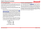
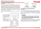
TB4
J2
+Terminal = 24 VDC
- Terminal is open
collector 100mA driver
for use with optional 100
decibel piezo
annunciator.
TB3
24 VDC power output
for remote devices such
as transmitters, lights,
relays etc. 350mA MAX
(see Figure 3.0)
TB4
5 amp resistive SPDT
(form C) dry contact relay
outputs. Use appropriate
diode / snubber devices
when switching inductive
loads.
TB5
Universal 100-240VAC
primary power source
terminals.
Important: GND terminal
3 must be tied to earth
for correct shielding of
incoming signals.
TB2
Dry contact input for use
with optional remote
Alarm Reset switch.
Wires must be shorter
than 10 feet & shielded
if longer than 2 feet.
TB1
Available for 24 VDC
primary power input.
May also be used as
battery back-up to AC
primary power source.
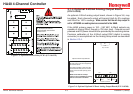
TIE TB5 GND to EARTH
J3
SHOCK HAZARD
RISK OF ELECTRICAL
SHOCK-DISCONNECT OR
TURN OFF POWER
BEFORE SERVICING THE
EQUIPMENT
WARNING:
For continued protection against
fire replace only with same type and rating
of fuse. (Part # = Littelfuse 217002)
AC POWER
L1 GNDL2
100-240 VAC
3
2
1
TB5
3 Watts MAX
~
.45A 50/60 Hz
Connections to J1 & J3 are not covered by CSA
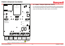
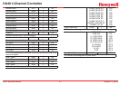
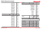
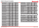
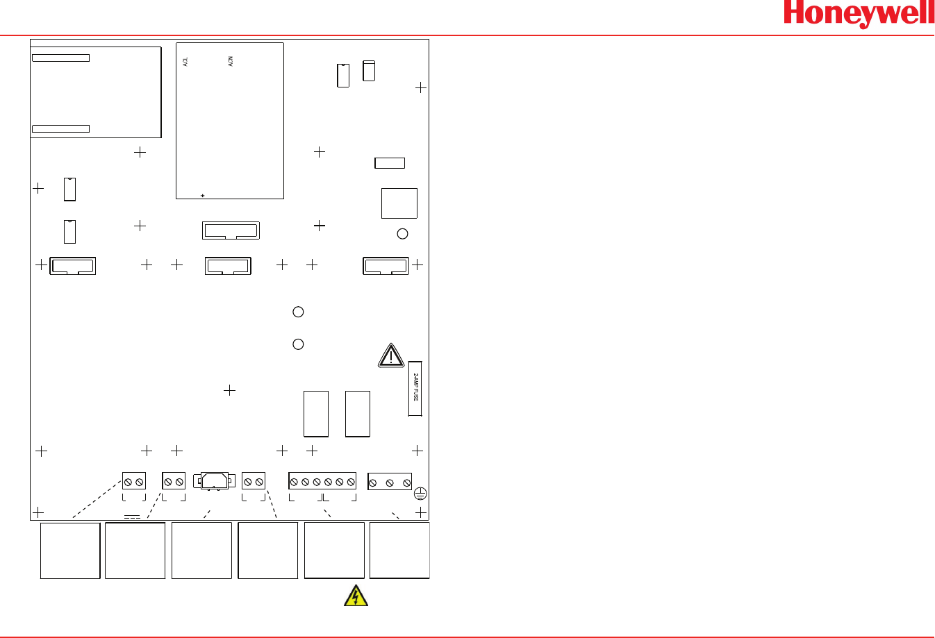
Figure 3-2. Motherboard Relays and Terminals
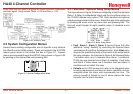
3�1 Input / Output Optional PCB’s
P1, P2 and P3 connectors on the motherboard offer unique positions
for I/O options described in this section. A screen appears briey after
power up indicating what options types are connected.