


HA40 4-Channel Controller
Revision 1 (07/08)
HA40 Technical Manual 2-9
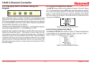
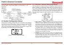
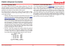
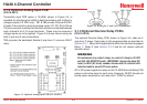
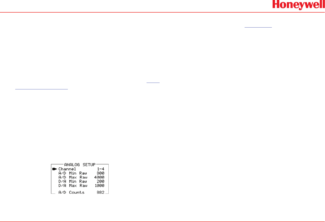
2�3�4 Analog Setup Menu
The system ANALOG SETUP menu allows setting the 12-bit A/D
(analog to digital) counts and the 10-bit D/A (digital to analog) counts
for each of the four channels. The live A/D counts value for the channel
selected is also shown on the bottom of this screen.
The default setting for A/D counts is 800 for Min and 4000 for Max.
This is based upon a 0-20mA input providing 0-4000 counts, or, 200
counts per mA input.
A/D Min / Max Raw counts menu entries dene the input counts •
value that cause Zero and Span readings as described in Input
Measurement Range. The default settings for each channel
are 800 to 4000 counts because the HA40 4-20mA input PCB
has a 12-bit analog to digital converter that yields 200 counts
per milliamp input. Standard 4-20mA inputs yield 800 counts at
4mA and 4000 counts at 20mA. However, if a special application
required the Zero reading at 6mA input and the Span reading
at 18mA input the correct A/D Min / Max Raw counts menu
entries would become 1200 to 3600.00.
D/A Min / Max Raw counts menu options dene the optional •
(future) 4-20mA output PCB’s input. Ideally, 200 to 1000 yields
a 4-20mA output but very slight modications may be needed
to provide precise 4mA and 20mA values for each channel.
Figure 2-11. Analog Setup Menu
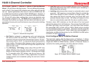
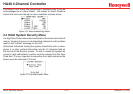
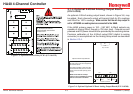
2�3�5 Horn / Acknowledge Menu
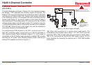
J2 on the motherboard (shown in Figure 3.2) is the driver output for
part # 1000-1892 optional 100dB piezo. Fault, Alarm1, Alarm 2, &
Alarm 3 menu options (shown in Figure 2-12) allow programming of
which alarms affect this piezo and whether by pulse or steady tones.
The HA40 display PCB is also equipped with a small audible piezo
that chirps when keys are pressed, providing an audible feedback to
the operator. It also may be set to audibly indicate alarm conditions
by entering ON into the Local Piezo menu item in Figure 2-12. This
piezo will then mimic the optional 100dB horn.