


HA40 4-Channel Controller
Revision 1 (07/08)
HA40 Technical Manual 2-7
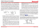
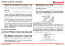
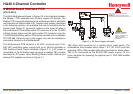
Unity Gain may be used at anytime to cancel incorrect calibrations
and start again. Unity means Offset = 0.00 and Gain = 1.00.
Figure 2-6. Cal Flow Chart
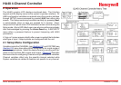
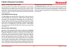
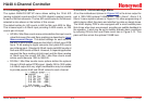
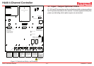
2�3 System Configuration Menus
Several items needing conguration are not specic to any channel
but affect the entire HA40 system. These are located in the SYSTEM
menus group shown in the dotted line box in Figure 2-7. System
menus are accessed through the SETUP menu shown in Figure 2-23
by pointing to the desired item and pressing Edit.
SETUP (firmware rev)
Channel 1
Channel 2
Channel 3
Channel 4
System
Security
History
Figure 2-7. System Conguration Menu
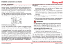
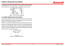
2�3�1 Standard / Optional Relay Setup Menus
The menu shown in Figure 2-8 allows conguring of both the standard
Relay 1 & Relay 2 motherboard relays and the six optional relays on
the 10-0222 discrete relay option PCB. Both standard and optional
relays are programmed in this menu. Select the relay to be congured
by pointing the arrow at the top menu item and pressing Edit. The
eld will scroll through all eight possible relays (2 standard and 6
optional).
Figure 2-8. Relay Setup Menu
Fault• , Alarm 1, Alarm 2, Alarm 3 menus (Figure 2-8) offer
additional “voting” exibility by controlling the channel alarm
combinations that will trip the selected relay. Each Votes entry
requires the specied quantity of that alarm to be active before
this relay activates. As illustrated in Figure 2-24 Standard Relay
1 activates when any 2 channels have Alarm 1 conditions,
PLUS, any one channel has an Alarm 2 condition. Fault Votes
and Alarm 3 Votes values are 0 therefore Fault and Alarm 3
conditions will not affect this relay.
Failsafe• set for YES causes this relay to be energized when
its voting requirements are false (no alarm condition) and de-
energized when the alarm vote requirements are true. The
primary benet of failsafe is loss of power places the relay
contacts into the alarm condition.