


HA40 4-Channel Controller
Revision 1 (08/08)
HA40 Technical Manual 3-4
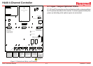
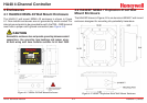
3�1�2 Optional Analog Input PCB
(P/N 10-0221)
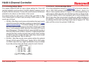
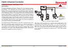
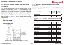
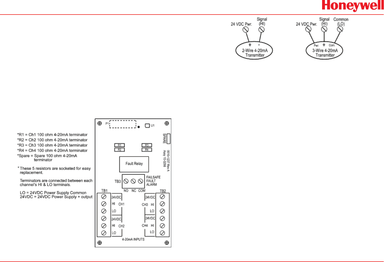
Transmitter input PCB option # 10-0298, shown in Figure 3-3, is
available for interfacing the HA40 to eld transmitters with 4-20mA or
voltage outputs (0-2 VDC max). TB1 & TB2 provide Channel 24VDC,
HI and LO terminals for receiving analog inputs. R1, R2, R3, & R4 are
100 ohm precision socketed termination resistors connected between
each channel’s HI & LO input terminals. These may be removed if
voltage inputs are to be applied. Figure 3-4 shows correct wiring for
both 2-wire and 3-wire transmitters.
TB3 provides the dedicated failsafe-5 amp-form C common FAULT
relay.
Figure 3-3. Optional Analog Input PCB (P/N 10-0221)
Figure 3-4. Wiring for 2- and 3-wire Transmitters
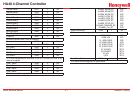
3�1�3 Optional Discrete Relay PCB’s
(P/N 10-0222)
The optional Discrete Relay PCB, shown in Figure 3-5, adds six 5
amp form C relays. Each relay is fully programmable as described in
Section 2.3.1. Many HA40 applications utilize the standard equipped
Relay 1 / Relay 2 (see Section 2.3.1) and do not require optional
discrete relays
Warning
All mechanical (dry contact) relays are rated at 5 Amp for 28 VDC
and 250 ~VAC RESISTIVE loads. IMPORTANT: Appropriate diode (DC
loads) or MOV (AC loads) snubber devices must be installed with
inductive loads to prevent RFI noise spikes.
AC or DC power supplies to relays on the 10-0222 Discrete Relay PCB
option must be the same for each relay. Example: 24VDC should not
be the power switched by one relay and 115VAC by others.