


HA40 4-Channel Controller
Revision 1 (08/08)
HA40 Technical Manual 3-6
3�2 MODBUS RS-232 / RS-485 Interface Option
(P/N 10-0253)
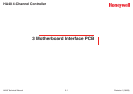
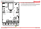
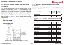
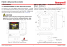
The 10-0253 Modbus option PCB add both RS-232 and RS-485
Modbus RTU slave ports. Figure 3-7 shows this optional PCB,
which mounts to connectors on the upper right corner of the HA40
motherboard. TB1 provides two pairs of T/Rx terminals and a oating
terminal for shield continuation. This makes it easy to multi-drop
HA40s onto an RS-485 cable without doubling wires into the same
screw terminals. RS-232 interface may be made by connecting to
DB9 connector S1. Section 3.3.1 lists all modbus registers and their
function codes.
Caution
Follow correct IEEE RS-232 and RS-485 installation guidelines when
using the 10-0253 option.
Figure 3-7. HA40 Modbus Interface Option (P/N 10-0253)
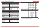
3�2�1 MODBUS Register And Function Code
Summary
The following table identies the available modbus RTU register
locations and function codes.
VARIABLE ALIAS
READ
FUNCTION
CODE
WRITE
FUNCTION
CODE
Read/Write Coils:
Alarm Ack/Reset 2001 1 5
note:
After writing a TRUE to this register, the HA40 automatically returns it to
FALSE.
Read Only Discrete:
Chan 1 Fault Alarm 12001 2 NA
Chan 1 Alarm 1 12002 2 NA
Chan 1 Alarm 2 12003 2 NA
Chan 1 Alarm 3 12004 2 NA
Chan 2 Fault Alarm 12005 2 NA
Chan 2 Alarm 1 12006 2 NA
Chan 2 Alarm 2 12007 2 NA
Chan 2 Alarm 3 12008 2 NA
Chan 3 Fault Alarm 12009 2 NA
Chan 3 Alarm 1 12010 2 NA
Chan 3 Alarm 2 12011 2 NA
Chan 3 Alarm 3 12012 2 NA
Chan 4 Fault Alarm 12013 2 NA
Chan 4 Alarm 1 12014 2 NA
Chan 4 Alarm 2 12015 2 NA
Chan 4 Alarm 3 12016 2 NA