


HA40 4-Channel Controller
Revision 1 (08/08)
HA40 Technical Manual 3-2
3 Motherboard Interface PCB
(P/N 10-0215)
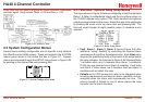
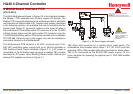
The HA40 Motherboard shown in Figure 3.2 is the interface between
the Display / CPU assembly and all other system I/O devices. The
Display / CPU assembly attaches to the motherboard with 4-standoffs
and connects via ribbon cable to S1. Several input options, described
in the following sections, are available that may be installed into the
Sensor Input Option P1 connector located on the lower left side of
the motherboard. The middle position P2 connector is for the 10-0223
4-20mA Output option and the right position P3 connector is for the
10-0222 Discrete Relay option. Other option devices such as Modbus
RTU RS-485, Ethernet and a data logger may also be installed to
connectors located on the Motherboard.
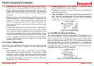
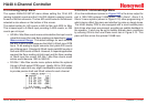
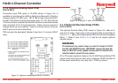
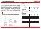
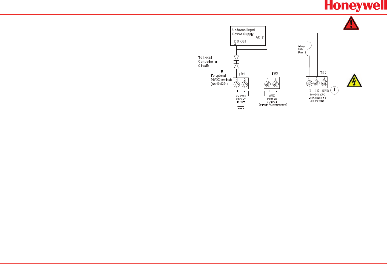
The Motherboard PCB contains a 24 VDC universal input (100-
240 VAC) switching power supply with up to 350mA available at
TB3 Auxiliary Power Output terminals (Figure 3.1). If AC power is
unavailable, or if a DC battery back-up supply is needed, TB1 provides
terminals for DC power input. Blocking diodes isolate internal and
external DC supplies as shown in Figure 3-1.
2 Amp, 250V, 5x20mm fuse located under
terminal cover.
WARNING: For continued protection against
fire replace only with same type and rating of fuse.
Universal Input
P
ower Supply
AC In
DC Out
+
To Local
C
ontroller
C
ircuits
+ - + -
L1 L2 GND
TB1
TB3
TB5
DC PW R
SUPPLY
IN PU T
AUX
POW ER
OUTPU T
100-240 VA C
.45A 50 60 Hz
AC POWER
SHOCK HAZARD
RISK OF ELECTRICAL
SHOCK - DISCONNECT OR
TURN OFF POWER
BEFORE SERVICING THE
EQUIPMENT
2-Amp
250V
Fuse
To optional
24VDC terminals
(p/n 10-0221)
(only with AC primary power)
Figure 3-1. DC Power Supply Schematic
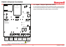
TB2 offers field terminals for a remote alarm reset switch. The
motherboard also includes alarm relays 1 & 2 (K1 & K2) and their
indicating LED’s. TB4 provides eld wiring terminals for these relays.
TB5 is for connection to the 85-240 VAC power source. J2 is a
2-pin connector for powering the optional part # 1000-1892 audible
annunciator.