


HA40 4-Channel Controller
Revision 1 (08/08)
HA40 Technical Manual 3-5
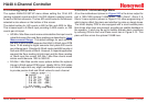
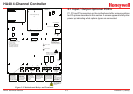
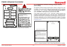
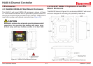
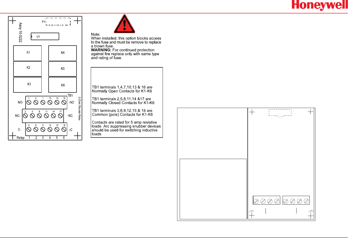
K1, K2, K3, K4, K5 & K6 are
programmable, as described
in section 2.3.1
Figure 3-5. Optional Discrete Relay PCB’s (P/N 10-0222)
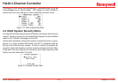
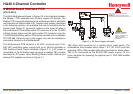
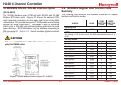
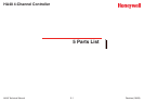
3�1�4 Optional 4-20mA Analog Output Board
(P/N 10-0308)
An optional 4-20mA analog output board, shown in Figure 3-6, may
be added. Each channel’s output will transmit 4mA for 0% readings
and 20mA for 100% readings. Make certain that the mA loop output is
set to LATCHING on reading devices connected to the HA40.
If the HA40 primary power is 100 – 240 VAC, 4-20mA outputs are
capable of driving 20mA through a 750 ohm load. Outputs are self
powered and DC power should not be provided by the receiving device.
Precision calibration of the 4-20mA output DAC (digital to analog
converter) is accomplished via the Analog Setup menu as described
in Section 2.3.4.
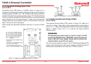
1 2 341 2 34
4-20mA OUTPUTS
CH1 CH2 CH3 CH4
+ -+ -+ -+ -
TB1
TB2
TB1
Assy # 10-0308
4-20mA Outputs are sourcing and
24 VDC power must not be supplied by
the receiver device
Loop Drive capability is 750 ohms with
nominal 85-240 VAC power or 24 VDC
power as the Controller primary power
supply.
Make certain that the mA loop
output is set to LATCHING on reading
devices connected to the HA40.
Optional 4-20mA Outputs Notes
Figure 3-6. Optional Optional 4-20mA Analog Output Board (P/N 10-0308)