


4500 Thermostat Installation Instructions
3-8
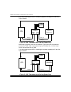
10. Once the 4500 is mounted, you need to set its DIP switch and 3-pin fan
control jumper. These procedures are described below.
Setting the DIP Switch
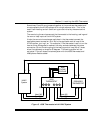
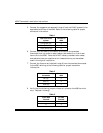
The 4500 includes a DIP switch for setting the address of the thermostat.
The 4286 phone access module can include up to 2 thermostats per system.
These are referred to as thermostats 1 and 2.
Set thermostat #1 DIP switch to address 01.
If there are 2 thermostats in the system the second must have its DIP switch
set to address 02.
If there is only one 4500 thermostat in the system, program the 4286 for
operation with thermostat #1 (see the section “Programming the 4286 to Add
Thermostats”). If there are two thermostats in the system, ask the user which
one will be used the most. The most commonly used thermostat should be
programmed as thermostat #1, since the voice menus allow setting of
thermostat #1 as soon as the thermostat setting menu is entered.
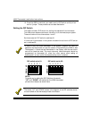
DOWN UP
DOWN UP
5 4 3 2 1
5 4 3 2 1
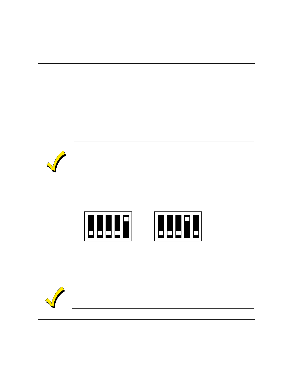
NOTE:
To assist you in setting the DIP Switches, the words
“UP” and “DOWN” are marked on the 4500 thermostat
printed circuit board, as shown here.
DIP switch set to 01:
DIP switch set to 02:
The words, “UP” and “DOWN” shown in the diagram of the DIP switches above,
are as marked on the thermostat printed circuit board.