


4500 Thermostat Installation Instructions
3-6
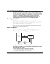
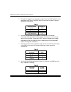
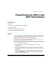
5. Connect the tagged wires removed in step 4 from the HVAC system to the
applicable terminals of the 4500. Refer to the following table for proper
connection information.
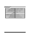
Table 1
Lead from HVAC
system
Terminal on
4500
Fan (green) (G) 8
Cool (yellow) (Y) 7
Heat (white) (W) 6
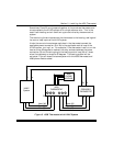
6. Connect a wire to each of the vacant terminals on the premises
thermostat that you noted in step 4 above, and make a run from those
terminals to the 4500. Note that HVAC industry standard color codes
and abbreviations are noted here, but these colors may not have been
used in the original installation.
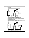
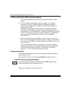
7. Connect the three wires installed in step 6 from the premises thermostat
to the 4500 referring to the following table for proper connection
information.
Table 2
Terminal on existing
thermostat
Terminal on
4500
Fan (G) 5
Cool (Y) 4
Heat (W) 3
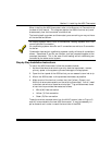
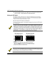
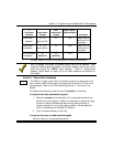
8. Verify that the following jumper wires are in place on the 4500 terminal
strip. Replace if missing:
Table 3
From 4500
Terminal
To 4500
Terminal
13
24