


— 7 —
HC24EO SERIES STEAMER
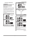
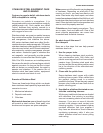
ELECTRICAL CONNECTIONS
: Electrical and grounding
connections must comply with the
applicable portions of the National
Electrical Code and/or other local
electrical codes.
When making electrical connections, use copper
wire suitable for at least 200°F (90°C). The
steamer must be grounded. The wiring diagram
is located on the inside of the right panel.
Steamers are wired for 3-phase and can be
converted to 1-phase by relocating the jumper
wires on the terminal block as shown on the
wiring diagram.
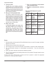
To Control
Transformer *
To Control
Transformer *
3-PHASE, 208 V
3-PHASE, 240 V
1-PHASE, 208 V
1-PHASE, 240 V
B
BL
BR
YL
BL
BR
YL
21
24
21
22
23
24
25
26
22
25
23
26
BL
BR
YL
BL
BR
YL
A
B
A
*Primary taps of Control Transformer must be connected
according to the appliance data plate voltage marking and
actual connected supply.
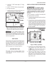
To Control
Transformer *
3-PHASE, 380 V
3-PHASE, 415 V
3-PHASE, 480 V
B
BL
BR
YL
BL
BR
1CON L1 – T1
2CON T2 – L2
1CON L2 – T2
2CON T3 –L3
2CON T1 –L1
1CON L3 - T3
YL
21
22
23
A
*Primary taps of Control Transformer must be connected
according to the appliance data plate voltage marking and
actual connected supply.
To Control
Transformer *
To Control
Transformer *
3-PHASE, 208/240 V
1-PHASE, 208/240 V
B
BL
BR
YL
BL
BR
YL
21
24
21
22
23
24
25
26
22
25
23
26
BL
BR
YL
BL
BR
YL
GN
RD
OR
GN
RD
OR
GN
RD
OR
GN
RD
OR
A
B
A
*Primary taps of Control Transformer must be connected
according to the appliance data plate voltage marking and
actual connected supply.
** For operation from a 208 V supply, all 6 elements are to
be connected as shown. For 240 V supply, disconnect and
insulate element leads with Orange, Green and Red markers.
Not used for
240V operation **