


Heat & Glo • RED40, RED40ST • 2155-900 Rev. o • 7/12
49
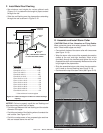
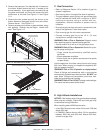
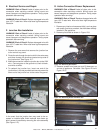
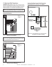
Figure 12.7 Junction Box Detail
1. Remove the one screw that secures the junction box
to the control tray panel.
2. Route the wire through the strain relief in the outer wrap
and down through the knockout located on top side of
the junction box. See Figure 12.7.
3. Make the connection inside the junction box to the 120V
wire. Connect green to the ground nut, black to black,
and white to white.
4. To reattach the junction box, insert one end of the
junction box in the slot provided and securely screw the
other end of the junction box to the control tray panel.
E. Electrical Service and Repair
WARNING! Risk of Shock! Label all wires prior to dis-
connection when servicing controls. Wiring errors can
cause improper and dangerous operation. Verify proper
operation after servicing.
WARNING! Risk of Shock! Replace damaged wire with
type 105° C rated wire. Wire must have high temperature
insulation.
In the event that the junction box may need to be ac-
cessed or installed after fi nish methods have been ap-
plied, access is possible by removing the valve assembly
(See Figure 11.2).
KNOCKOUT
KNOCKOUT
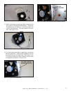
G. Active Convection Blower Replacement
WARNING! Risk of Shock! Label all wires prior to dis-
connection when servicing controls. Wiring errors can
cause improper and dangerous operation. Verify proper
operation after servicing.
WARNING! Risk of Shock! Replace damaged wire with
type 105° C rated wire. Wire must have high temperature
insulation.
F. Junction Box Installation
WARNING! Risk of Shock! Label all wires prior to dis-
connection when servicing controls. Wiring errors can
cause improper and dangerous operation. Verify proper
operation after servicing.
WARNING! Risk of Shock! Replace damaged wire with
type 105° C rated wire. Wire must have high temperature
insulation.
1. Remove any interior enhancement kit(s), such as glass
rock media, granite or porcelain, that have been already
installed in the appliance.
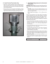
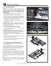
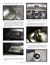
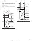
2. Remove pilot shield as shown in Figure 12.8.
Figure 12.8 Removing Pilot Shield
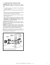
Figure 12.9 Removing Screws from Base Pan.
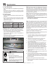
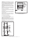
3. Remove screws from base pan and lift base pan up
and out of appliance. Set aside. See Figure 12.9 and
Figure 12.10.
Figure 12.10 Lifting Base Pan Up and Out.