


Heat & Glo • RED40, RED40ST • 2155-900 Rev. o • 7/1246
A. Wiring Requirements
NOTICE: This appliance must be electrically wired
and grounded in accordance with local codes or, in the
absence of local codes, with National Electric Code
ANSI/NFPA 70-latest edition or the Canadian Electric
Code CSA C22.1.
• Wire the appliance junction box to 110-120 VAC. This is
required for proper operation of the appliance.
• A 110-120 VAC circuit for this product must be protected
with ground-fault circuit-interrupter protection, in compliance
with the applicable electrical codes, when it is installed in
locations such as in bathrooms or near sinks.
• Low voltage and 110 VAC voltage cannot be shared
within the same wall box.
WARNING! Risk of Shock or Explosion! DO NOT wire
110V to the valve or to the appliance wall switch. Incorrect
wiring will damage controls.
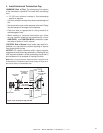
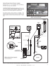
B. IntelliFire Ignition System Wiring
• Wire the appliance junction box to 110 VAC for proper
operation of the appliance.
WARNING! Risk of Shock or Explosion! DO NOT wire
IPI controlled appliance junction box to a switched circuit.
Incorrect wiring will override IPI safety lockout.
• Refer to Figure 12.5, IntelliFire Pilot Ignition (IPI) Wiring
Diagram.
• This appliance is equipped with an IntelliFire control valve
which operates on a 3 volt system.
• Plug the 3-volt AC transformer into the appliance junction
box to supply power to the appliance.
12
12
Electrical Information
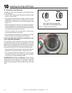
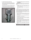
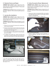
C. Optional Accessories Requirements
• This appliance ships standard with a wall switch and may
use a remote control.
Wiring for optional Hearth & Home Technologies approved
accessories should be done now to avoid reconstruction.
Follow instructions that come with those accessories.
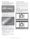
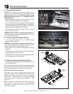
Optional Remote Control Receiver
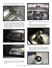
The junction box, control module, light controller and
wall switch receiver can be accessed thru the air space
between the fi rebox front and the lower-front fi nishing
cover panel. The decorative front and glass assembly
must be removed to access these components. See
Figure 12.1.
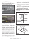
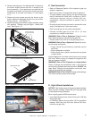
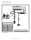
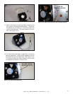
Note: If the fan is moved from one side to the other,
the junction box must also move. See appropriate
confi guration in relation to the valve in Figure 12.3. The
valve does not move.
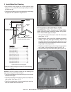
Figure 12.1. Valve Cavity (Lower Access Panel Removed)
THERMODISC
VALVE
MODULE
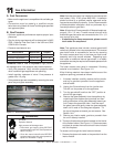
Figure 12.2. Valve Cavity
JUNCTION
BOX
OPTIONAL
REMOTE
CONTROL
MODULE
FAN
INSTALLED ON
RIGHT
VALVE
FAN
INSTALLED ON
LEFT
JUNCTION
BOX
VALVE
CONTROL
MODULE
OPTIONAL
REMOTE
Figure 12.3. Controls Location Diagram
FAN ASSEMBLY
FAN ASSEMBLY
JUNCTION BOX
JUNCTION BOX