


Heat & Glo • RED40, RED40ST • 2155-900 Rev. o • 7/1244
A. Fuel Conversion
• Make sure the appliance is compatible with available gas
types.
• Conversions must be made by a qualified service
technician using Hearth & Home Technologies specifi ed
and approved parts.
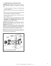
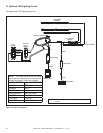
B. Gas Pressure
• Optimum appliance performance requires proper input
pressures.
• Gas line sizing requirements will be determined in ANSI
Z223.1 National Fuel Gas Code in the USA and CAN/
CGA B149 in Canada.
• Pressure requirements are:
WARNING! Risk of Fire or Explosion! High pressure
will damage valve. Low pressure may cause explosion.
• Verify inlet pressures. Verify minimum pressures when
other household gas appliances are operating.
• Install regulator upstream of valve if line pressure is
greater than 1/2 psig.
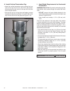
• Valve pressure taps are accessible by removing the outer
panel tray and glass assembly.
11
11
Gas Information
Gas Pressure Natural Gas Propane
Minimum inlet pressure 5.0 in. w.c. 11.0 in. w.c.
Maximum inlet pressure 10.0 in. w.c. 13.0 in. w.c.
Manifold pressure 3.5 in. w.c. 10.0 in. w.c.
Fire Risk.
Explosion Hazard.
High pressure will damage valve.
• Disconnect gas supply piping BEFORE
pressure testing gas line at test pressures
above 1/2 psig.
• Close the manual shutoff valve BEFORE
pressure testing gas line at test pressures
equal to or less than 1/2 psig.
WARNING
Note: This appliance does include a manual gas shutoff
valve that is located in the valve compartment. This manual
gas shutoff valve is accessible for service by removing
the outer access panel tray or the base pan and burner
assembly and inner access windows. Depending upon
local code, an additional manual gas shutoff, in a readily
accessible area may be required and located upstream from
the appliance.
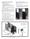
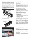
The lower access cover panel is removable if fi nishing
material is not installed. See Figure 11.2.
If the fi nishing materials have been installed around the
appliance opening, proceed as follows:
Note: Have the gas supply line installed in accordance with
local codes, if any. If not, follow ANSI 223.1. Installation
should be done by a qualifi ed installer approved and/or
licensed as required by the locality. (In the Commonwealth
of Massachusetts installation must be performed by a
licensed plumber or gas fi tter).
Note: A listed (and Commonwealth of Massachusetts ap-
proved) 1/2 in. (13 mm) T-handle manual shut-off valve
and fl exible gas connector are connected to the 1/2 in. (13
mm) control valve inlet.
• If substituting for these components, please consult
local codes for compliance.
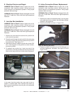
1. If already installed, carefully remove the front media
and tray or granite or porcelain from the appliance
and set aside.
2. Unplug the 3V transformer from the junction box.
This will turn the power off to the appliance.
3. Turn the gas shutoff handle to the “OFF” position to
shut off the gas supply.
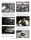
4. Remove the glass assembly from the appliance by
unlatching the two bottom spring latches and then
pulling the bottom of the glass assembly toward you
until it clears the glass latch tabs. Hold the top of
the glass frame and gently lower the glass assembly
down until it rests on the side glass supports. Tilt
the top of the glass out toward you and remove. See
Section 14.H.
5. Remove any interior media, granite or porcelain from
the unit if already installed.
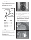
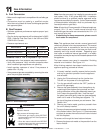
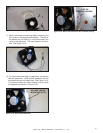
6. There are three access windows located on the interior
of the fi rebox bottom. See Figure 11.1. Remove screws
and plate to access the manual shutoff valve included
with this fi replace.
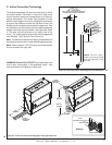
To access unit through the lower bottom windows:
1. Remove the glass rock media or the porcelain from the
interior fi rebox.
Figure 11.1. Valve Pressure Taps.