


Heat & Glo • RED40, RED40ST • 2155-900 Rev. o • 7/12
47
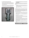
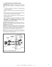
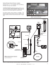
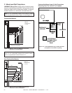
NOTE: 1. Ignition module, valve, pilot, and
wall switch operate on 3 volts. 120 VAC is
required at junction box.
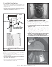
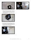
Optional Remote Control Receiver Location
A battery back up is not compatible with the RED40 or
RED40ST and may not be installed.
CAUTION! DO NOT install battery back up. Battery back
up is not compatible with this appliance. Battery pack and
batteries will not withstand appliance temperatures.
Figure 12.4. Required Location of Optional Remote Control
Receiver. (Heat shield removed)
REMOTE RECEIVER
An optional remote control receiver is available. The
optional remote control receiver must be installed in the
specifi c location under the heat shield as shown in Figure
12.4.
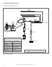
INTERMITTENT
PILOT IGNITOR
IGNITION
MODULE
3 VAC
FAN
PLUG-IN
3V TRANSFORMER
HIGH
TEMP
SWITCH
LOW VOLTAGE
SEE NOTE 1
IGNITION
MODULE
(3V)
FLAME SPARKER/
SENSOR
LOW VOLTAGE
SEE NOTE 1
VALVE
GROUND
REMOTE
CONTROL
NEUTRAL
ORG
WHITE
GROUND TO
FIREPLACE
CHASSIS
HIGH LIMIT
SWITCH
JUMPER
JUMPER
JUMPER
BRN
BRN
WIRE HARNESS
VALVE
GREEN
ELECTRICAL
ACCESS KNOCKOUT
GREEN
FAN
BLACK WIRE CAN BE
PLUGGED INTO ANY OF #1 - #5
LOCATIONS ON THE HOT SIDE
JUMPER WIRE
CAN BE
PLUGGED INTO
ANY OF #1 - #5
LOCATIONS
ON THE
NEUTRAL SIDE
SENSOR
WIRE
IGNI
WI
R
THERMO SNAP DISC
BATTERY PACK
WALL SWITCH
WIRE ASSEMBLY
WIRES
(TO BROWN)
TO WALL
SWITCH WIRE
OR REMOTE
WIRE HARNESS
WIRE HARNESS
Figure 12.5 IntelliFire Pilot Ignition (IPI) Wiring Diagram with Wall Switch or Remote