


9
A
B
C
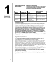
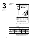
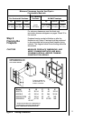
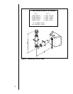
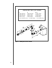
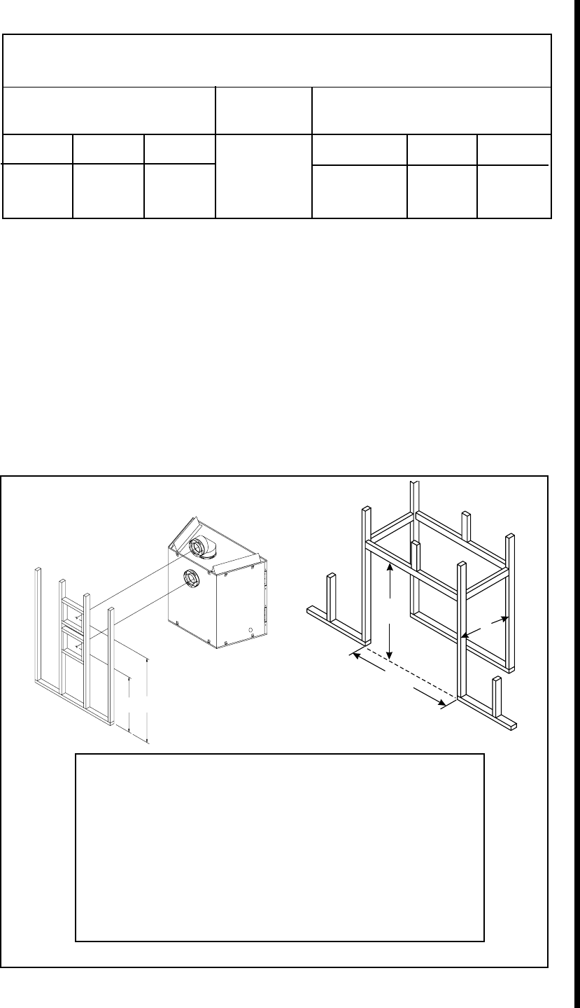
Framing should be
constructed of 2 X 4
lumber or heavier.
Model A B C D E
6000TR 42 38 1/4 22 42 26 1/4
6000XLS 42 38 1/4 22 N/A 26 1/4
6000XLT-CDN 42 38 1/4 22 42 N/A
6000ARCH 42* 41 7/8 22 53 5/8 N/A
48 1/4
**
* SURROUND IN FRONT OF FINISHED WALL
** SURROUND FLUSH WITH FINISHED WALL
NOTE: DIMENSIONS SHOWN IN INCHES
D
E
SHOWS CENTER OF12" X 12"
VENT FRAMING HOLES FOR
TOP & REAR VENTING.
Figure 4. Framing Dimensions
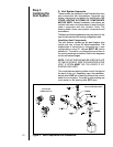
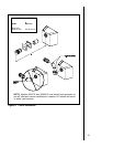
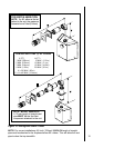
Minimum Clearances from the Vent Pipe to
Combustible Materials
For Vertical
For Horizontal Sections Sections At Wall Firestops
Top Bottom Sides Top Bottom Sides
3 inches 1 inch 1 inch 1 inch 2-1/2 inches 1/2 inch 1 inch
(75 mm) (25 mm) (25 mm) (25 mm) (63.7 mm) (13 mm) (25 mm)
For minimum clearances, see the direct vent
termination clearance diagrams on pages 28 and 30 in
this manual.
Step 2
Framing the
Fireplace
Fireplace framing can be built before or after the
fireplace is set in place. Framing should be positioned
to accommodate wall coverings and fireplace facing
material. The diagram below shows framing reference
dimensions.
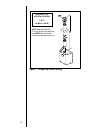
CAUTION
MEASURE FIREPLACE DIMENSIONS, AND
VERIFY FRAMING METHODS AND WALL
COVERING DETAILS, BEFORE FRAMING
CONSTRUCTION BEGINS.