


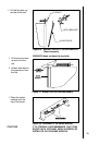
35
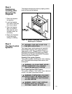
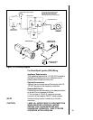
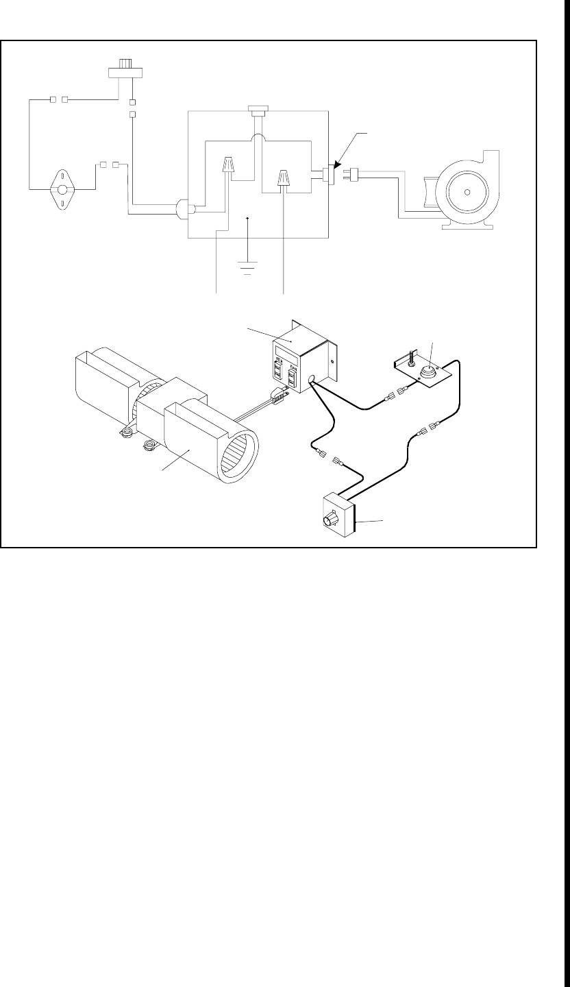
Figure 32. Fan Wiring Diagram
For Direct Spark Ignition (DSI) Wiring
Appliance Requirements
This appliance requires that 110-120 VAC be wired to
the factory installed junction box. Maintain correct
polarity when wiring the junction box.
Optional Accessories
Optional fan and remote control kits require that 110-
120 VAC be wired to the fireplace junction box.
Remote Wall Switch
Position the remote wall switch in the desired position
on a wall. Run a maximum of 25 feet
(7.8 m) or less of 16 A.W.G. minimum wire and
connect it to the fireplace ON/OFF switch pigtails.
NOTE
Electrical wiring must be installed by a licensed
electrician.
CAUTION
LABEL ALL WIRES PRIOR TO DISCONNECTION
WHEN SERVICING CONTROLS. WIRING
ERRORS CAN CAUSE IMPROPER AND
DANGEROUS OPERATION. VERIFY PROPER
OPERATION AFTER SERVICING.
NOTE: IF ANY OF THE ORIGINAL WIRE
AS SUPPLIED WITH THE APPLIANCE
MUST BE REPLACED, IT MUST BE
REPLACED WITH TYPE 105 C RATED WIRE.
O
JUNCTION BOX
VARIABLE SPEED CONTROL
TEMPERATURE
SENSOR SWITCH
WHT
GRN
BLK
BLK
110-120 VA
C
BLOWER
BLOWER RECEPTACLE
BLK
BLK
BLK
BLK
WHT
GROUND
WHT
BLK
BLK
BLK
FAN
TEMPERATURE
SENSOR SWITCH
SPEED CONTROL
(RHEOSTAT)
JUNCTION BOX