


10
VENT SYSTEM
TERMINATION KITS
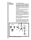
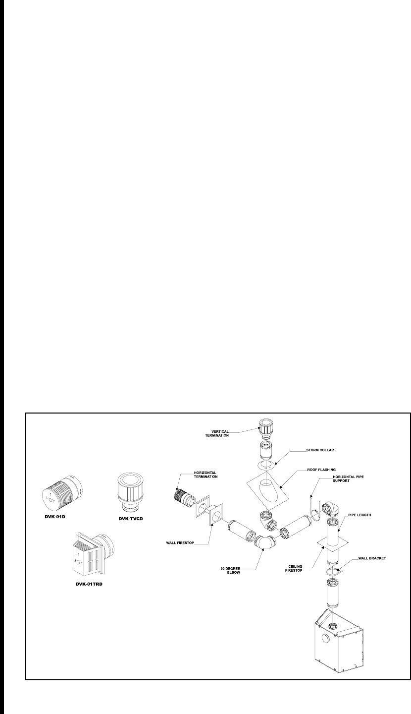
VENT SYSTEM COMPONENTS
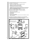
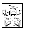
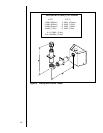
Figure 5. Vent Components and Terminations
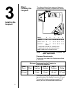
Step 3
Installing the
Vent System
A. Vent System Approvals
These models are approved to use D-series direct vent
pipe components and terminations. Approved vent
system components are labeled for identification. NO
OTHER VENTING SYSTEMS OR COMPONENTS
MAY BE USED. Detailed installation instructions are
included with each vent termination kit and should be
used in conjunction with this Installers Guide. The
drawing below shows vent system components and
terminations.
The flame and ember appearance may vary based on the
type of fuel burned and the venting configuration used.
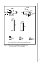
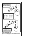
Identifying Vent Components
The vent systems installed on this gas fireplace may
include one, two, or three 90°
elbow assemblies. The
relationships of vertical rise to horizontal run in vent
configurations using 90° elbows MUST BE strictly
adhered to. The rise to run relationships are shown in
the venting drawings and tables. Refer to the diagrams
on the next several pages.
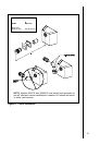
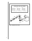
NOTE: TWO 45° ELBOWS MAY BE USED IN PLACE
OF ONE 90° ELBOW. RISE TO RUN RATIOS IN THE
VENT SYSTEM MUST BE FOLLOWED IF 45°
ELBOWS ARE USED.
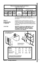
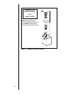
This model has vent starting collars on both the top and
the back of the unit. Depending upon the installation,
decide which ONE set of starting collars will be used to
attach the vent system. The starting collar sealing cap
must remain on the starting collar NOT used.