


22
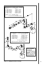
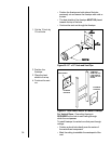
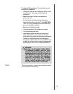
2. Continue Adding Vent Components
To continue adding vent components in accordance
with the pre-planned vent system configuration:
Ensure that each succeeding vent component is
securely fitted and locked into the preceding com-
ponent in the vent system.
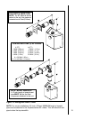
Figure 18. Adding Venting Components
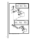
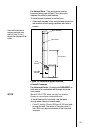
3. Install Support Brackets
For Horizontal Runs - The vent system must be
supported every five (5) feet of horizontal run by a
horizontal pipe support.
To install support brackets for horizontal runs:
Place the pipe supports around the vent pipe.
Nail the pipe supports to the framing members.
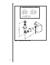
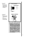
Figure 17.
If the installation is for a termination cap attached directly
to the fireplace, skip to the sections, Install Firestops
and Vent Termination.
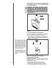
WARNING: FOR MODEL 6000ARCH: MAKE
CERTAIN THAT THE FIBERGLASS INSULA-
TION BAND IS PACKED INTO THE SPACE
BETWEEN THE 11-INCH DIAMETER TOP
PIPE HEAT SHIELD AND THE STARTER PIPE.
SEE FIGURE 17.
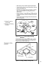
90° elbows may be installed
and rotated to any point
around the preceding com-
ponents vertical axis. If an
elbow does not end up in a
locked position with the pre-
ceding component, attach
with a minimum of two (2)
sheet metal screws.
Continue adding vent com-
ponents, locking each suc-
ceeding component into
place.
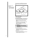
!