


32
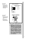
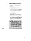
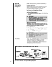
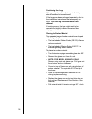
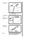
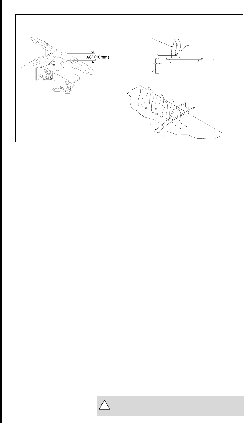
STANDING PILOT
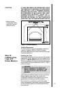
NOTE: FLAMES TOO
CLOSE TO THE
CERAMIC INSULATORS
CAN CAUSE NUISANCE
LOCKOUTS AND
ELECTRODE FAILURE.
DSI IGNITION
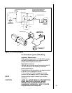
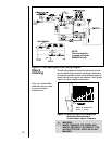
Figure 29. Gas Controls Systems
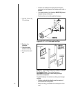
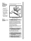
Step 6
The Gas
Supply Line
NOTE: Have the gas supply line installed by a
qualified service technician in accordance with all
building codes.
NOTE: Before the first firing of the fireplace, the
gas supply line should be purged of any trapped air.
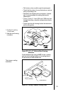
NOTE: Consult local building codes to properly size
the gas supply line leading to the 1/2 inch
(13 mm) hook-up at the unit.
This gas fireplace is designed to accept a 1/2 inch
(13 mm) gas supply line. To install the gas supply line:
A listed 1/2 inch (13 mm) manual shut-off valve and
a listed flexible gas connector are connected to the
1/2 inch (13 mm) inlet of the control valve.
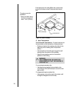
The gas line may be run from either side of the
fireplace provided the hole in the outer wrap does
not exceed 2 inches in diameter and it does not
penetrate the airtight box.
The gap between the supply piping and gas ac-
cess hole can be plugged with non-combustible
insulation to prevent cold air infiltration.
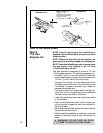
Locate the gas line access hole in the outer casing
of the fireplace.
Open the fireplace lower grille, insert the gas sup-
ply line through the gas line hole, and connect it to
the shut-off valve.
When attaching the pipe, support the control so that
the lines are not bent or torn.
After the gas line installation is complete, use a soap
solution to carefully check all gas connections for
leaks.
WARNING: DO NOT USE AN OPEN
FLAME TO CHECK FOR GAS LEAKS.
!
1/4" (6mm)
IGNITOR
3/8” (10mm)
CERAMIC
INSULATOR