


WattMaster WHP Section 4
4-4 Start-Up and Troubleshooting
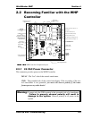
2.0 WHP Controller
Overview
2.1 How It Works
2.1.1 Initialization
On system powerup the COMM LED remains extinguished for five seconds. After this
delay, the COMM LED will blink out the address of the controller (Address Switch
Setting). The COMM LED will then extinguish for another five seconds and then begin
to blink for a twenty second startup delay. At the conclusion of this twenty second period,
the COMM LED will begin blinking a diagnostic code every ten seconds. This code is
described later in this document. The duration of a powerup initialization sequence is
roughly one minute.
During this initialization period, the controller retrieves all operating setpoints from its
non-volatile EEPROM memory and initializes all outputs to an OFF condition.
Note: All future references to the Water Source Heat Pump Controller in this docu-
ment use WHP as the designation.
2.1.2 Operating Summary
At all times, after the conclusion of the initialization sequence, the WHP performs a
specific set of operating instructions in the following order: (a - g repeat continuously)
a. Read Analog Inputs for Temperatures and Overrides.
b. Check the RS-485 communications port for any new setpoints from the System
Manager and keeps the status updated for the System Manager.
c. If the push-button override is active, it checks the timer to see if the override is
finished.
d. Calculates the current occupied/unoccupied mode from its internal week sched-
uling.
e. Calculates what state the output relays and analog output should be set to.
f. Updates the diagnostic COMM LED blinking.
g. Stores data in the internal trend log if ready for another log.