


WattMaster WHP Section 4
4-26 Start-Up and Troubleshooting
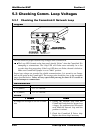
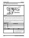
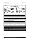
5.3.3 Checking the CommLink II Driver
Diagram
Overvie
w
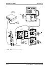
This test checks for proper Network loop voltages coming from the CommLink II.
The Loop LED (located on the front panel) should “flicker” when the CommLink II is
attempting to communicate. The Loop LED will flicker more noticeably for a few
seconds when first powered up. If the LED does not flicker, the unit is not function-
ing.
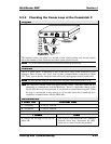
Proper loop voltages are essential for reliable communications. It is normal to see fluctua-
tions at this point on the CommLink II. The average value should be close to the acceptable
range described below. Values will vary upon initial powerup for about 10-15 seconds as
the unit attempts to communicate.
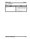
Measurements
T – G
(SHLD)
2.4 - 2.5 Volts DC
R – G
(SHLD)
2.5 - 2.7 Volts DC
Action
If voltages are too high or too low on either
side
1. The CommLink II has a damaged comm
driver chip. Replace the driver chip.
See instructions in section 1.3.11 for
“Comm Driver Chip Replacement”.
2. The CommLink II is defective.