


WattMaster WHP Section 4
Start-Up and Troubleshooting 4-35
5.4 Troubleshooting Loop Controller
5.4.1 Checking the Loop Controller Analog Inputs
Diagram Overvie
w
12V
GND
AIN1
AIN2
AIN3
AIN4
AOUT2
GND
+
-
R
SET METER TO
READ DC VOLTS
ALL READINGS ARE TAKEN
WITH THE (-) LEAD OF THE
METER ON THE GND
TERMINAL
+
AIN5
AIN7
GND
AOUT1
-
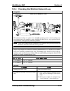
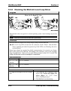
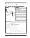
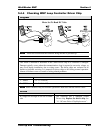
The analog input wiring can be checked at the
Loop Controller by checking voltages on the
Analog Input Connector.
If any of the RWT, SWT, OAT inputs read
greater than 5.0 volts then it is OPEN (no
sensor is connected), an input that reads less
than 0.1 volts is SHORTED. Check for wiring
problems before proceeding.
The Loop Pressure, Manual Reset, Phase
Loss, Fire Alarm and Request to Run inputs
should read greater than 5.0 volts if the at-
tached contact is OPEN and less than 0.5 volts
if the contact is CLOSED (contacts CLOSE
between the input and GND). The Fire Alarm
and Request to Run contacts are located on
the Analog Input Expansion Board.
The Loop Controller must be pow-
ered for these tests.
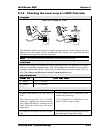
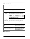
Measurements
Ignore readings for any connections which are not used in the
equipment.
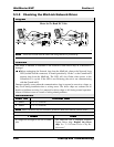
AIN1
Return Water Temp
1.9 volts (100°F) - 3.6 volts (40°F)
Typical is 2.5 volts @ 77°F
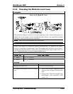
AIN2
Supply Water Temp
1.9 volts (100°F) - 3.6 volts (40°F)
Typical is 2.5 volts @ 77°F
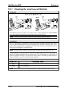
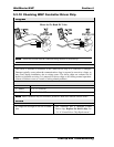
AIN3
Proof of Flow
When used with the Low Pressure Switch option:
If the input is OPEN, the voltage will be greater than 5.0 volts
If the input is CLOSED, the voltage will be less than 0.5 volts
When used with 0-50 PSI Loop Pressure Sensor option:
5.1 VDC = 50 PSI – 0.0 VDC = 0 PSI