


WattMaster WHP Section 4
Start-Up and Troubleshooting 4-33
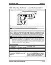
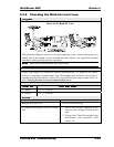
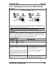
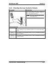
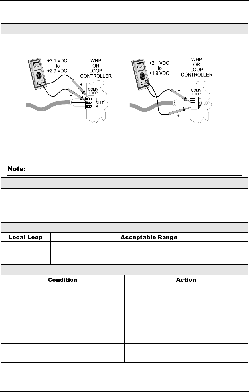
5.3.9 Checking the Local Loop at a WHP Controller
Diagram
Meter Set To Read DC Volts
The indicated readings are typical of a normal operating system. Actual readings may vary
slightly due to the number of units installed and other factors. Any significant deviation
from these values generally indicates a problem.
These tests assume that a MiniLink is connected and powered up.
Overvie
w
Proper loop voltages are essential for reliable communications. It is normal to see fluctua-
tions on an operating communications loop. The average value should be close to the ac-
ceptable range described below. Values will vary upon initial powerup for about 30-45 sec-
onds. The voltages may fluctuate as normal communications occur.
Measurements
T – SHLD 2.9 - 3.1 Volts DC
R – SHLD 1.9 - 2.1 Volts DC
Action
If meter reads between 2.4 VDC and 2.5
VDC
The Comm Loop “floats” at 2.4 - 2.5VDC
when only controllers are connected to the
loop. When a MiniLink is connected it will
“bias” each side of the loop to the values
listed above.
1) No CommLink II or MiniLink is con-
nected and powered up.
2) If a CommLink II or MiniLink is con-
nected, look for “open” wiring.
If voltages are too high or too low on either
side
One or more devices connected to this loop
have damaged Comm Driver chips.