


WattMaster WHP Section 4
Start-Up and Troubleshooting 4-27
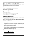
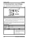
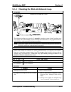
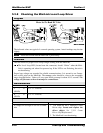
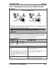
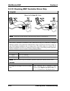
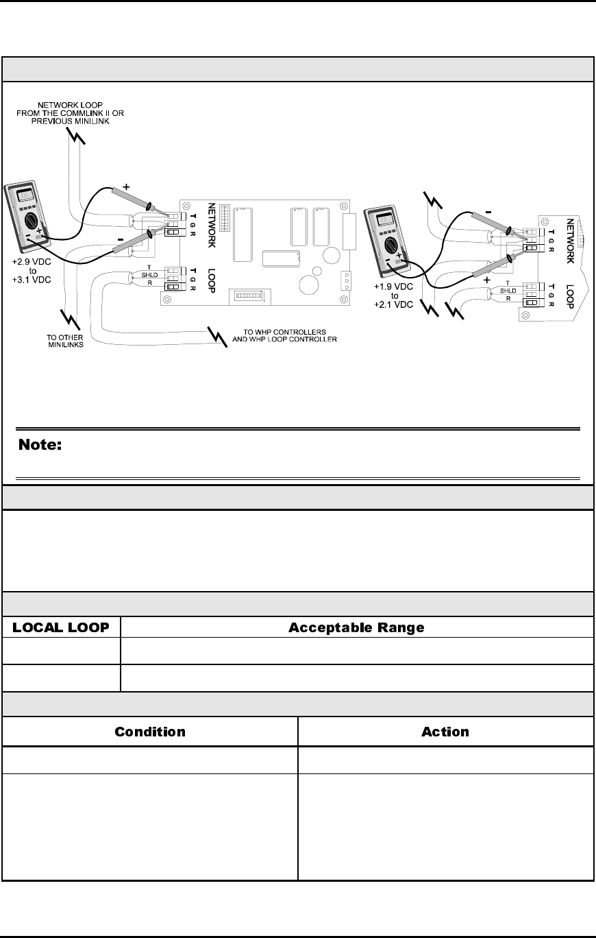
5.3.4 Checking the MiniLink Network Loop
Diagram
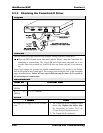
Meter Set To Read DC Volts
The indicated readings are typical of a normally operating system. Actual readings may
vary slightly due to the number of units installed and other factors. Any significant devia-
tion from these values generally indicates a problem.
These tests assume that the CommLink II is connected and powered, and that all
MiniLinks which are connected are also powered.
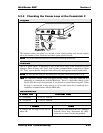
Overvie
w
Proper loop voltages are essential for reliable communications. It is normal to see fluctua-
tions on an operating communications loop. The average value should be close to the ac-
ceptable range described below. Values will vary upon initial powerup for about 15-30
seconds as normal communications occur.
Measurements
T - G (SHLD) 2.9 - 3.1 Volts DC
R - G (SHLD) 1.9 - 2.1 Volts DC
Action
Readings near Zero Volts Check for shorted wiring.
If voltages are too high or too low on either
side
1. One or more devices connected to this
loop may have damaged Comm driver
chips.
2. Wiring errors. Check for multiple loops
“cross connected”, short circuits, etc.