


Section 4
Start-Up and Troubleshooting
5.0 Troubleshooting ...................................................... 21
5.1 General Troubleshooting........................................................................................21
5.1.1 Communications Troubleshooting Checklist.................................................21
5.1.2 General Troubleshooting Checklist ...............................................................22
5.2 Alarms......................................................................................................................23
5.3 Checking Comm. Loop Voltages.............................................................................24
5.3.1 Checking the CommLink II Network Loop ...................................................24
5.3.2 Checking the Comm Loop at the CommLink II ............................................25
5.3.3 Checking the CommLink II Driver................................................................26
5.3.4 Checking the MiniLink Network Loop..........................................................27
5.3.5 Checking the MiniLink Network Driver........................................................28
5.3.6 Checking the MiniLink Local Loop...............................................................29
5.3.7 Checking the Local Loop at MiniLink...........................................................30
5.3.8 Checking the MiniLink Local Loop Driver ...................................................32
5.3.9 Checking the Local Loop at a WHP Controller.............................................33
5.3.10 Checking WHP Controller Driver Chip.........................................................34
5.4 Troubleshooting Loop Controller ..........................................................................35
5.4.1 Checking the Loop Controller Analog Inputs................................................35
5.4.2 Checking the Loop Controller Outputs..........................................................37
5.4.3 Checking the Local Loop at a WHP Loop Controller....................................38
5.4.4 Checking WHP Loop Controller Driver Chip ...............................................39
5.4.5 Comm Driver Chip Replacement...................................................................40
5.5 Temperature Sensor Resistance Chart ...................................................................41
5.6 Pressure Sensor Voltage Chart...............................................................................42
Notes: ............................................................................ 43
Table of Figures
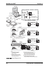
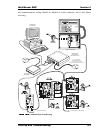
Figure 4-1: System Wiring Overview.............................................................................2
Figure 4-2: Communications Loop Routing...................................................................3
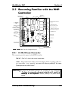
Figure 4-3: WHP Controller Component Layout ...........................................................5
Figure 4-4: Typical WHP Controller Wiring Diagram...................................................8
Figure 4-5: Loop Controller Inputs & Outputs.............................................................13
Figure 4-6: Diagnostic LED Blink Codes.....................................................................14
Figure 4-7: Diagnostic LED Blink Codes.....................................................................15
Figure 4-8: Communications Loop Wiring ..................................................................18
Figure 4-9: MiniLink Address Switch Setting.............................................................19
Figure 4-10: WHP Controller Address Switch Setting...............................................20
Figure 4-11: Comm Driver Chip Replacement............................................................40