


WattMaster WHP Section 4
Start-Up and Troubleshooting 4-25
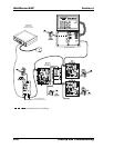
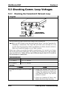
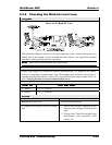
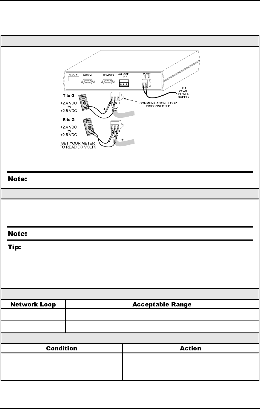
5.3.2 Checking the Comm Loop at the CommLink II
Diagram
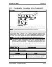
The indicated values are typical of a normal system, actual readings may deviate slightly
due to the number of units connected and other system specific factors.
All of the connected Minilinks should be powered up for this test.
Overvie
w
This is a “quick check” to determine if any of the driver chips on the Network loop are
damaged. Since all units will “float” both of their communications connections at about
2.45 Volts, you can quickly check the Network loop by unplugging it at the CommLink II.
Be sure that the loop you are testing does not have a short circuit from T to R.
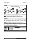
The Loop LED (located on the front panel) should “flicker” when the CommLink II is
attempting to communicate with the MiniLinks. There is a noticeable change in the
flicker when the loop is disconnected, if you observe a normal functioning unit. When
the loop is reconnected it may take up to 60 seconds before the CommLink II re-
establishes communications with the MiniLinks.
Measurements
T – G (SHLD) 2.4-to-2.5 Volts DC
R – G (SHLD) 2.4-to-2.5 Volts DC
Action
If voltages are too high or too low on
either side
One or more of the MiniLinks has a damaged
Network driver chip. Disconnect the Mini-
Links one at a time to isolate the problem.