


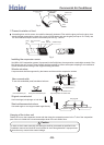
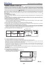
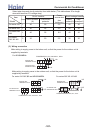
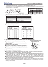
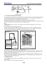
(7) Installation work for air outlet ducts
Calculate the draft and external static pressure and select the length, shape and blowout.
A Blowout duct
2-spot, 3-spot and 4-spot with 200 type duct are the standard specifications. Determine the number of spots
based on following table.
Note (1) Shield the central blowout hole for 2-spot.
(2) Shield the blowout hole around the center for 3-spot.
Limit the difference in length between spots at less than 2:1.
Reduce the length of duct as much as possible.
Reduce the number of bends as much as possible. (Corner R should be as larger as possible.)
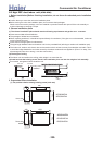
Use a band. etc. to connect the main unit and the blowout duct flange.
Conduct the duct installation work before finishing the ceiling.
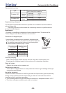
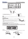
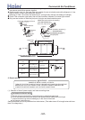
(8) Connection of suction, exhaust ducts
(a) Duct connection position
i) Fresh air inlet
Inlet can be selected from the side or rear faces depending on the working conditions.
Use the rear fresh air inlet when the simultaneous intake and exhaust is conducted.
(Side inlet cannot be used.)
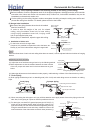
ii) Exhaust (Make sure to use also the suction.)
Use the side exhaust port.
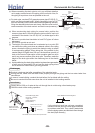
Good exampleBad exampleBad example
Ceiling surface
Heat
insulation
Suction panel
(Silent panel)
Air conditioner main unit
B Special blowout
(Option)
A Blowout duct
(Optional or marketed item)
C
Hole for check
special inlet (option)
(with air filter)
inlet duct
(optional or
marketat item)
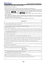
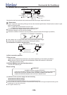
Electric wiring
WARNING
DANGER OF BODILY INJURY OR DEATH
TURN OFF ELECTRIC POWER AT CIRCUIT BREAKER OR POWER SOURCE BEFORE
MAKING ANY ELECTRIC CONNECTIONS. GROUND CONNECTIONS MUST BE
COMPLETED BEFORE MAKING LINE VOLTAGE CONNECTIONS.
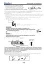
(1) Selection of size of power supply and interconnecting
Precautions for Electric wiring
Electric wiring work should be conducted only by authorized personnel.
Do not connect more than three wires to the terminal block. Always use round type crimped terminal lugs with
insulated grip on the ends of the wires.
Use copper conductor only.
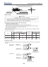
Exhaust hole
State seeing from top of unit
Side fresh air inlet
Rear fresh air inlet
Fig.1
Fig.2
>a__WcU[S^ <[c >a`V[e[a`Wc
-100-