


Ð 36 Ð
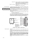
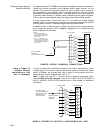
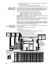
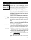
2. Connect 3 wires from terminals 1, 2, and 3 on the right side of the VIM module
to the control, as follows:
a. Terminal 1 to the ground terminal (30) on the control.
b. Terminals 2 and 3 to the ÒhandsetÓ terminals (26 & 27) on the control.
6139AV Audio
Connections To
The VIM Module
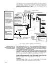
Each 6139AV 2-way Keypad requires a shielded 2-wire connection to the VIM
Module. Splice the flying leads of the supplied SA550AB Audio Bus connector
to this shielded cable, then plug the connector into the 6139AV keypad's J5
connector located on the right of the keypad, just beneath the PC board.
Connect the 6139AV keypad(s) to the VIM module as follows:
Keypad 1 (and Keypad 4, if used): to terminals 1, 2, and 3
Keypad 2 (and Keypad 5, if used): to terminals 4, 5, and 6
Keypad 3 (and Keypad 6, if used): to terminals 7, 8, and 9.
IMPORTANT: Connect the shield at the VIM module, but not at the
keypad, as shown in the VIM connection diagram.
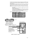
If more than three 6139AV keypads are used (up to six 6139AV keypads can be
supported), connect as follows: keypad 4 in parallel with keypad 1, keypad 5 in
parallel with keypad 2, and keypad 6 in parallel with keypad 3.
Terminal 10 can, if you wish, be connected to the audio output on the 4285
module (terminal 6 or 7), if the phone module is used in the system. This will allow
the voice output heard through a telephone via the phone module to be heard
through the built-in speaker in the 6139AV keypad(s).
Programming
Information For the
VIM Module
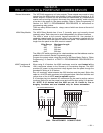
When programming the system, use #93 Menu ModeÐDevice Programming to
program the following:
¥ Device address as set by the DIP switches (01Ð15).
¥ Device type "7".
¥ Partition 1, partition 2, automatic or all.
¥ Voice session timeout duration (5 min, 10 min, 15 min, or no timeout).
VIM
(VOICE INTERFACE MODULE)
KEYPADS
#1 AND #4
KEYPADS
#2 AND #5
KEYPADS
#3 AND #6
AUDIO
CONNECTIONS
USE 2-WIRE SHIELDED CABLE TO CON-
NECT 2-WAY VOICE KEYPADS TO VIM
MODULE. CONNECT SHIELD AT VIM
MODULE, BUT NOT AT KEYPAD.
DIP
SWITCH
ON
1
5
1
2
4
5
6
7
8
9
10
3
4-PIN
HEADER
1
2
3
HANDSET
RING
HANDSET
TIP
YELLOW
NOT USED
RED
BLACK
GREEN
TO CONTROL’S
HANDSET
TERMINALS
MICRO-
PROCESSOR
CONNECTOR WITH 4
FLYING LEADS CON-
NECTS TO CONTROL’S
KEYPAD TERMINALS
SHIELD
l
l
l
l
SHIELD
l l
SHIELD
PHONE
MODULE
AUDIO OUTPUT
{
CONNECT TO CONTROL’S KEYPAD TERMINALS
USING CONNECTOR SUPPLIED WITH KEYPAD
USE SA550AB AUDIO CONNECTOR SUPPLIED WITH KEYPAD
ON
1
2
3
4
5
OFF ON
{
(SHOWN SET FOR
ADDRESS “7”)
(SUPPLIED WITH VIM)
IMPORTANT:
SET DIP SWITCHES
BEFORE CONNECTING
4-PIN CONNECTOR
FROM CONTROL’S
KEYPAD TERMINALS.
†
COMPATIBLE WITH SELECTED KEYPADS AND CONTROLS
TO EARTH GROUND
STATUS
LEDs
R
G
*
ADDRESS 4 RESERVED FOR VISTA INTERACTIVE PHONE MODULE
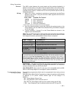
VIM STATUS LED FUNCTIONS
RED ON TALK SINGLE
RED FLASH TALK TO ALL
GREEN ON VOX MODE
BOTH ON LISTEN SINGLE
BOTH FLASH LISTEN ALL
ALT. FLASH WAIT ID CODE
BOTH OFF IDLE
SWITCH
POSITION
1
2
3
4
5
DIP SWITCH SETTINGS
1
2
3
4
5
6
7
8 9 10 11 13 171612 1514 2221201918 23 26
30
29
282524 27
–
ON
–––
–
–
–
–
––
–––––
–
–
–––
–
––
–
–
–
–
––
–
–
–
–
–
–
–––
–
–
–
––
–
–
–––
–
–––––––––
–
–
–
–
––
––
–
–
–
–
–
–
––
ON
ON
ON
ON
ON
ON
ON
ONON
ON
ON
ON
ON
ONONONONONON
ON
ONONON
ON
ONON
ON
ON
ON
ON
ONONONONON
ONONONONONONONONONONONON
ON
ON
ON
ONONON
ONONONONONONONON
ON
ONONONONON
ON
ON
ON
ONONONON
*
ON
J5
J5
i
i
TO J5
2-WAY
†
VOICE
KEYPAD
2-WAY
†
VOICE
KEYPAD
2-WAY
†
VOICE
KEYPAD
J5
IMPORTANT: SET DIP
SWITCHES BEFORE CON-
NECTING 4-PIN PLUG.
{
{
{
{
{
CONNECTING THE ADEMCO VOICE INTERFACE MODULE (VIM)