


Ð 30 Ð
Remote Keypad Sounder
Operation & Wiring
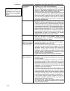
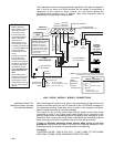
An optional Amseco PAL 328N can be used for installations where it is desired to
remote the sounds produced by the keypad's built-in piezo sounder for one
partition. The panel will remote all sounds (i.e. alarm, trouble, chime, entry/exit,
etc.) produced by the keypad's built-in sounder except for the short clicks
associated with keypad key depression. One application of this feature might be
to produce chime sounds in a location which is distant from the panel's keypads.
This can also be accomplished using relay outputs (see Output Relay section).
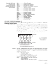
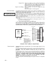
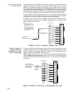
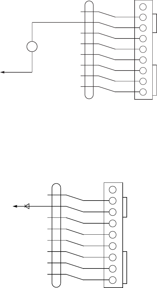
If used, program field 1*46 must be set to "2" to enable the remote keypad
sounder option, and the Amseco piezo must be connected between the panel's
auxiliary power and the J7 connector trigger output as shown below.
In addition, field *15 must be used to select the partition whose keypad sounds
are to trigger the sounder. Zone 7 must be assigned to be a keyswitch zone
(even if keyswitch is not used).
1 2 3 4 5 6 7 8 9
GRAY
YELLOW
WHITE
RED
GREEN
BROWN
BLUE
BLACK
GROUND
OUT 1
GROUND
OUT 2
GROUND
OUT 3
GROUND
OUT 4
J7 CONNECTOR
IF USED.
1. OUT 1 IS NO LONGER
USABLE FOR OPEN/CLOSE
OR GROUND START (SEE
FIELD 1*46).
2. OUT 2, 3, 4 CAN STILL BE
USED TO PROVIDE ALARM
STATUS INDICATIONS OR
TO OPERATE A KEYSWITCH
(SEE FIELD *15).
N/U
4142TR CABLE
BLACK
–
AMSECO PAL-328N
PIEZO SOUNDER
+
RED
TO AUX POWER +
TERMINAL 6
(10mA CURRENT DRAW)
REMOTE KEYPAD SOUNDING CONNECTIONS
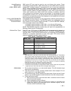
Using A Trigger To
Activate Another
ManufacturerÕs AAV
Unit (if necessary)
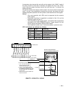
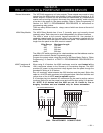
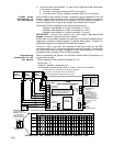
If using an Audio Alarm Verification module from another manufacturer, and a
voltage trigger will be used to activate the module, make connections as shown
below. In addition, set program field 1*46 to option 3, and program zone 5 for
response type 10; also, program field 1*60 for Ò1Ó.
Note:
If field 1*60 is set for Ò1Ó, zone 5 cannot be used as a protection zone,
and the EOLR must be removed. Refer to the
2-WAY VOICE KEYPADS &
AUDIO ALARM VERIFICATION
section later in this manual for additional
information.
1 2 3 4 5 6 7 8 9
GRAY
YELLOW
WHITE
RED
GREEN
BROWN
BLUE
BLACK
GROUND
OUT 1
GROUND
OUT 2
GROUND
OUT 3
GROUND
OUT 4
J7 CONNECTOR
N/U
4142TR CABLE
TO AUDIO ALARM
VERIFICATION MODULE
(AAV) FALLING EDGE
TRIGGER INPUT
ON THE AAV UNIT
DIODE INCLUDED
WITH EOLR
PACKAGE
USING A TRIGGER TO ACTIVATE A NON-ADEMCO AAV UNIT