


Ð 35 Ð
Section 8. 2-WAY VOICE KEYPADS &
AUDIO ALARM VERIFICATION (AAV)
General Information
IMPORTANT: Audio alarm
verification reports only on the
primary phone number.
The VISTA-40 features 2-way voice capability when used with the Ademco Voice
Interface Module (VIM) and 6139AV 2-way voice keypads.
U
L
The AAV option cannot be used in UL installations
An Audio Alarm Verification (AAV) module, such as the Ademco VIM module,
permits voice dialog between an operator at a central station and a person at the
alarm installation, for alarm verification. This feature is supported only if alarm
reports are programmed to be sent to the primary phone number. Setting field
1*60 to "0" selects the VIM module.
After all messages have been sent during a reporting session to the primary
phone number, the control will trigger the AAV if at least one of the messages
was an alarm report. If the central station has a 685 receiver Rev 4.6 or higher, the
panel can be either programmed for auto callback or Òlisten in to followÓ. If the
receiver is not a 685 or if the Rev number is lower than 4.6, the AUTO
CALLBACK feature must be enabled in order for the 2-way voice module to
function.
Once triggering occurs, the control will give-up the phone line to the AAV
module, without breaking connection with the central station. During the time the
module is active, all sirens and all continuous keypad sounds in all partitions will
be shut off. When the module indicates that the audio alarm verification session is
completed, all keypad sounds will be restored. Sirens will be restored if the alarm
timeout period has not expired.
As part of its fail-safe software, the control will limit all audio alarm verification
sessions to 5, 10, or 15 minutes, selectable by programming via #93 (this is
because once the session begins, the AAV module controls the duration). If a
new fire/panic alarm should occur during a session, the control will break phone
connection and send the new fire/panic alarm report, then re-trigger AAV mode.
All other dialer messages triggered during on-going conversation will be held until
either the AAV module signals that it is inactive, or the AAV timeout occurs.
Using the VIM Module
and 6139AV Keypad
To provide 2-way voice capability, the system requires a VIM (Voice Interface
Module) and at least one 6139AV 2-way voice keypad in each partition being
monitored. The system supports up to six 6139AV keypads. The 685 Receiver at
the central station requires software version 4.6 or higher, unless the AUTO
CALLBACK feature is enabled.
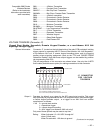
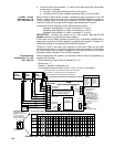
Setting The DIP
Switches on the VIM
Module
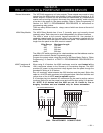
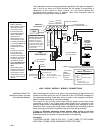
Set the VIM's DIP switches to the desired device address (01-15) referring to the
VIM wiring diagram on the next page. Address 04 is reserved for the 4285 phone
module. NOTE: The VIM reports as zone 93 for supervision faults.
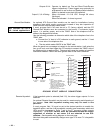
VIM Module
Connections To
the Control
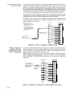
The VIM connects to the control's keypad terminals in the same manner as any
other keypad. The connection must be home run to the control. The VIM also
connects to the control's "handset" terminals. See the VIM connection diagram
on the next page.
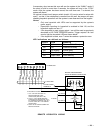
1. Connect the VIM module to the control's keypad terminals using the
connector with Red, Black, Green, and Yellow wires (supplied with the
keypad).
a. Attach the 4-pin keypad connector with 4 flying leads to the 4-pin header
on the right side of the VIM module (see the VIM connection diagram on
the next page for location of the 4-pin header).
b. Connect the flying leads from this connector to the keypad terminals on
the control, as follows:
Red wire to terminal 6.
Black to terminal 7
Green to terminal 8
Yellow to terminal 9.