


Ð 34 Ð
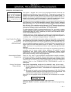
Zone descriptors must also be programmed, regardless of the type of keypads in
use. If this is not done, the Phone Module will be unable to annunciate a
description of the zone(s) in alarm, trouble, etc. (the Phone Module will
annunciate zone numbers only). In addition, relay voice descriptors can be
programmed if output relays are being used.
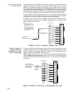
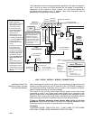
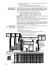
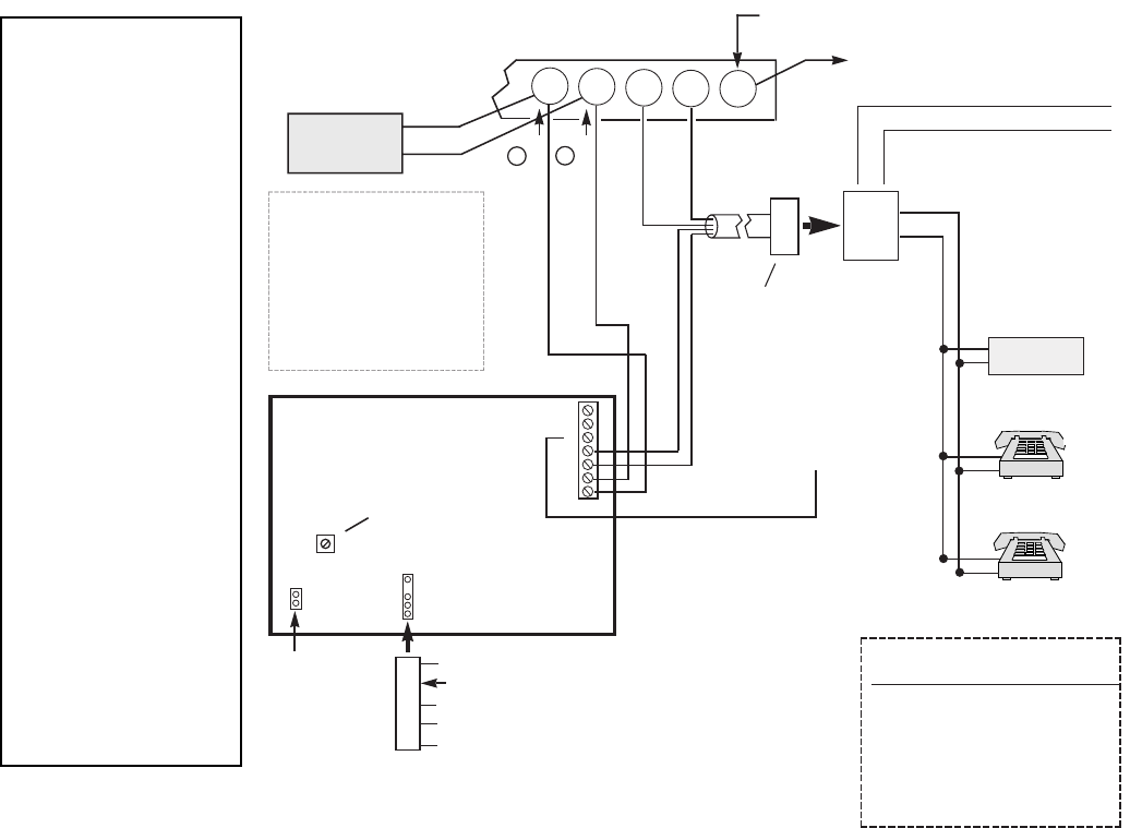
WIRING NOTES:
1. Wire the 4285 Phone
Module exactly as shown,
using a direct-connect
cord and RJ31X jack.
2. If Touch-tones are not
present following phone
access to the security
system
via an on-
premises phone
, try re-
versing the pair of wires
connected to terminals 3 &
4 on the 4285, and the pair
of wires connected to
terminals 26 & 27 on the
control.
3. Connection to the incom-
ing Telco line via an
RJ31X jack and direct-
connect cord, as shown in
this diagram, is essential,
even if the system is not
connected to a central
station. The 4285 will not
function if this is not
done.
4. Phone module ground
terminals must terminate
to ground on the control.
5. There must be 7 volts or
greater while phone is "off-
hook" for phone module to
operate.
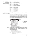
27
ANSWERING
MACHINE
TERMINALS
ON CONTROL
TO EARTH GROUND
(COLD WATER PIPE, ETC.)
Æ
NOT INSTALLER
ADJUSTABLE
UNUSED
KEYED
HEADER
s
4285
VOICE MODULE
123456 7
YELLOW: TO DATA OUT (term. 7)
NO CONNECTION
RED: TO AUX (+) (term. 5)
BLACK: TO AUX. GROUND (–) (term.4)
GREEN: TO DATA IN (term. 6)
CONNECTOR
WITH FLYING
LEADS
TO CONTROL
PANEL
TERMINALS
USED FOR
KEYPAD
CONNECTIONS
PREMISES
ANSWERING
MACHINE
AND PHONES
s
Handset
Incoming
Telco Line
TIP
RING
RJ31X
JACK
PLUG
DIRECT
CONNECT
CORD
TIP
RING
GROUND TERMINAL
MUST CONNECT TO
ON 4285 (TIP)
MUST CONNECT TO
ON 4285 (RING)
GREEN
RED
1
2
s
ss
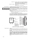
INCOMING TELCO LINE
TO GND TERMINAL
(30) ON CONTROL
GRAY (RING)
BROWN (TIP)
4285
TERMINAL ASSIGNMENTS
1 - TIP
2 - RING
PHONE INPUT
3 - TIP
4 - RING
PHONE OUTPUT
5 - GROUND
6 -
7 -
AUDIO OUT 1
(FOR FUTURE USE)
}
}
}
{
{
IMPORTANT NOTE FOR
EXISTING INSTALLATIONS:
ANY EXISTING WIRES
CONNECTED TO THE
"HANDSET" TERMINALS
ON THE CONTROL MUST
BE MOVED FROM THERE
TO TERMINALS 3 AND 4
ON THE 4285.
26
28
29
30
CALLER ID
UNIT
*
*
*
NOTE: IF THE TELEPHONE HAS BUILT-IN CALLER ID,
THE CALLER ID FUNCTION MAY NOT WORK
.
CA38A
IN
CANADA
}
4285 PHONE MODULE WIRING CONNECTIONS
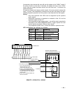
Installations Where The
Telephone System Includes
An Answering Machine
When accessing the system via a phone, the programmed 2-digit phone code
should be entered during the first 20 seconds of the OUTGOING message on
the answering machine (preferably during a pause in the outgoing message),
before it begins recording an incoming message.
The reason for entry of the phone code during a pause is that touch tones
(produced by entry of the 2-digit phone code) might not be received by the
security system while an answering machine's outgoing voice message is on the
phone line. Also, entering the 2-digit phone code
before
the answering machine
starts recording will prevent the phone code tones from being recorded.
If there is difficulty obtaining phone access when trying to use this
procedure, instruct the end user to re-record the outgoing message on the
answering machine, but leave a 2-second pause at its beginning.
Example:
Ê
(2-SECOND PAUSE)Ê THIS IS 555Ð1212. I CAN'T COME TO THE PHONE
JUST NOW. PLEASE LEAVE A MESSAGE AFTER THE TONE.