


Ð 11 Ð
PHONE LINE CONNECTIONS
Standard Phone Line
Connections
IMPORTANT!: If using a 4285 Phone Module, phone connections must be
made exactly as shown in the
PHONE MODULE
section, even if the system is
not programmed to communicate with a monitoring station. The 4285 Phone
Module will not function unless the system is wired exactly as
described.
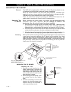
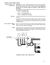
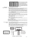
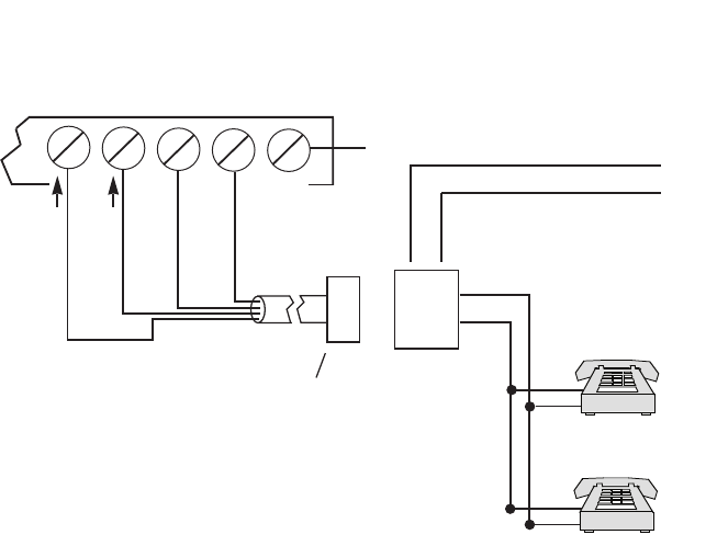
Incoming phone line and handset wiring is connected to the main terminal block
as follows (refer to Diagram below):
TB1-26: Local Handset (TIP)
TB1-27: Local Handset (RING)
TB1-28: Incoming Phone Line (TIP)
TB1-29: Incoming Phone Line (RING)
Warning:
To prevent the risk of shock, disconnect phone lines at telco jack before servicing
the panel.
If you want to connect the control panel to phone lines that require ground start
capability, you must use a 675 Ground Start Module must be used. This module
is triggered by one of the outputs on the connector labeled J7 (see
VOLTAGE
TRIGGERS
section).
Voice Interface Module
(VIM)
Be sure to connect the VIM unit to the control's handset terminals 26 and 27.
Refer to the
2-WAY VOICE KEYPADS AND AUDIO ALARM VERIFICATION
section later in this manual for wiring diagram.
PABX If the communicator is connected to a telephone line inside a PABX, be sure the
PABX has a back-up power supply that can support the PABX for 24 hours. Many
PABXs are not power backed up and connection to such a PABX will result in a
communication failure if power is lost.
TERMINALS
ON CONTROL
EARTH GROUND
INCOMING TELCO LINE
Æ
Handset
Incoming
Telco Line
TIP
RING
RJ31X
JACK
PLUG
DIRECT
CONNECT
CORD
TIP
RING
GROUND
s
ss
PREMISES
PHONES
s
{
{
BROWN (TIP)
GRAY (RING)
GREEN (TIP)
RED (RING)
26 27 28 29 30
26 27
28 29
30
STANDARD PHONE LINE CONNECTIONS