


Ð 28 Ð
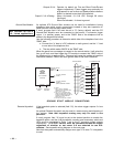
Outputs 2 & 4: Operate, by default, as Fire and Silent Panic/Duress
triggers respectively. These triggers may optionally be
programmed to act as Arm and Ready status indicators
when it is desired to use the 4146 keyswitch.
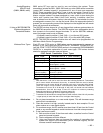
Output 2, 3, & 4 Rating: When Activated: 10Ð13.8 VDC through 5K ohms
(2mA max).
When De-activated: 1k ohms to ground.
Ground Start Module
Not intended for use in
UL Listed applications.
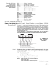
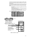
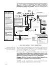
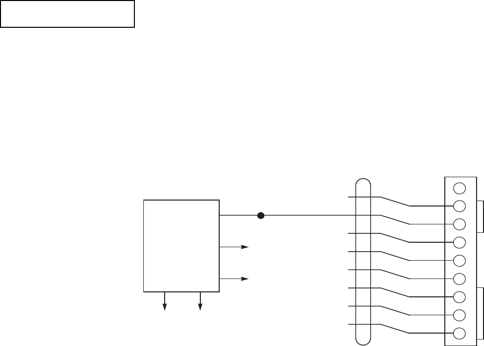
An optional 675 Ground Start module can be used for installations having
telephone lines which require ground start instead of loop start operation to
obtain dial tone from the telco central office.
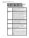
If used, program field 1*46 must be set to "0" (factory default) and the 675
Ground Start Module must be connected to the panel's J7 connector trigger
output 1, to auxiliary power, and to the "RING" side of the telephone line as
shown in the diagram that follows.
Use the following procedure to determine which side of the telephone line is the
"RING" side:
a. Connect the "+" lead of a DC voltmeter to earth ground, and the "Ð" lead
to one side of the telephone line.
b. The wire which reads +50VDC is the "RING" side.
When the panel has a message to transmit to the central station, it will seize the
line, go off hook, and then trigger the 675 module to connect the "RING" side of
the telephone line to earth ground. The panel will cause the module to break the
connection between "RING" and earth ground when a dial tone is obtained.
1 2 3 4 5 6 7 8 9
GRAY
YELLOW
WHITE
RED
GREEN
BROWN
BLUE
BLACK
GROUND
OUT 1
GROUND
OUT 2
GROUND
OUT 3
GROUND
OUT 4
J7 CONNECTOR
IF USED.
1. OUT 1 IS NO LONGER
USABLE FOR OPEN/CLOSE
(SEE FIELD 1*46).
2. OUT 2, 3, 4 CAN STILL BE
USED TO PROVIDE ALARM
STATUS INDICATIONS OR TO
OPERATE A KEYSWITCH
(SEE FIELD *15).
3. THE 675 IS NOT UL LISTED.
N/U
4142TR CABLE
GROUND START
TRIGGER
BLUE
BLACK
VIOLET
BROWN GREEN
TO TELCO
RING
TO EARTH
GROUND
675
GROUND
START
MODULE
(CUT ORANGE
JUMPER)
TO AUX. POWER
TERM. 7
TO AUX. POWER
TERM. 6
(50mA CURRENT DRAW
GROUND START MODULE CONNECTIONS
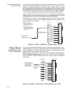
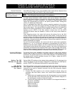
Remote Keyswitch If the keyswitch option is selected (field *15), the alarm trigger outputs 2Ð4 are
disabled.
An optional Remote Keyswitch can be used for remote arming and disarming of
the system. Note that keyswitch arming may only be used in one
partition.
If used, program field *15 must be set to the desired partition to enable the
keyswitch option, and the 4146 keyswitch's normally open momentary switch and
LEDs must be connected to Zone 7 and to the J7 connector trigger outputs
respectively. A 2k EOL resistor must be connected across the switch
regardless of whether or not zones 2Ð8 are selected to use EOL
resistors. See keyswitch wiring diagram on the next page.
Note that the system automatically assigns zone type 10 to zone 7 if a keyswitch
is used.