


Ð 15 Ð
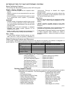
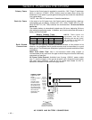
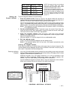
Wire Gauge Maximum Length
#22 gauge 450 feet
#20 gauge 700 feet
#18 gauge 1100 feet
#16 gauge 1750 feet
NOTE: The length of all wire runs combined
must not exceed 2000 feet when
unshielded quad conductor cable is used
(1000 feet if shielded cable is used.)
If more than one keypad is wired to a run,
then the above maximum lengths must be
divided by the number of keypads on the
run (i.e. the maximum length would be 225
feet if two keypads are wired on a #22
gauge run).
Setting the
Keypad Address
To set the keypad's address, do the following:
1. Enter the address mode: Power-up (plug-in) the keypad. Within 60 seconds of
system power-up, press and hold down the [1] and [3] keys at the same time for 3
seconds. (If unable to enter address mode, power-up and try again.)
The current keypad address will be displayed, and the cursor will be under the "tens"
digit. If 10 seconds have passed with no key entry, the keypad automatically exits
address mode. You must then power down, power-up and start address mode again.
Note: The keypad will not enter address mode if the panel to which it is connected
is in programming mode.
2. Set the current address to "00": Press [0] to clear the current "tens" digit. The
cursor will move to the "ones" digit position. Press [0] to clear the current "ones" digit.
The cursor will move back to the "tens" digit position.
3. Enter the keypad's address: Enter the proper "tens" digit of the keypad's
address. The cursor will move to the "ones" digit position. Enter the proper "ones"
digit of the keypad's address.
Note that address "31" sets the keypad to the non-addressable mode.
4. Exit the address mode:
Press [*] to save the displayed address and exit address mode.
Note: If 10 seconds passes with no key entry, the keypad automatically exits
address mode.
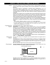
Viewing the Keypad Address
Press and hold down the [1] and [3] keys at the same time for about 3 seconds. The
current address will be displayed. No key entry is allowed in this mode. Press any key to
exit or wait 10 seconds to exit the viewing mode.
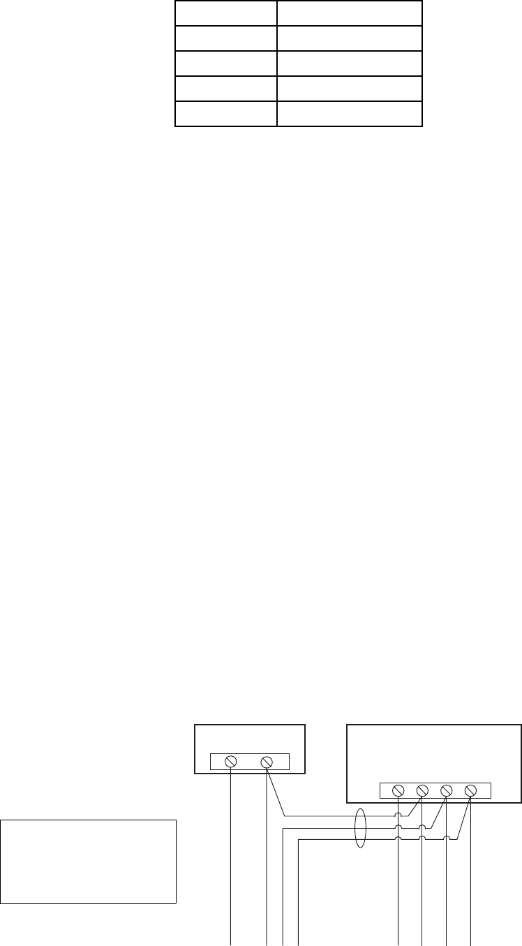
Powering Additional
Keypads
Up to five (5) 6139 keypads can be powered from the auxiliary power output provided
that the 750mA rating is not exceeded. The backup battery will supply power to these
keypads in the event that AC power is lost.
Additional keypads, up to the system maximum of 16, can be connected to the
system by using a regulated, 12VDC power supply (e.g., 488-12 supplies 12V,
500mA). Use a UL Listed, battery-backed supply for UL installations.
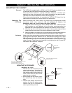
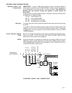
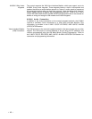
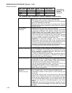
Connect additional keypads as shown below, using the keypad wire colors shown.
Make sure to observe the current ratings for the power supply used.
IMPORTANT
Common (Ð) of auxiliary
power supply must be
connected to (Ð) terminal
7 of the control panel.
SUPPLEMENTARY
POWER SUPPLY
+
–
CONTROL
TERMINAL STRIP
AUX AUX
.
DATA DATA
+–
IN OUT
6789
IMPORTANT:
MAKE CONNECTIONS
DIRECTLY TO SCREW
TERMINALS AS SHOWN.
MAKE NO CONNECTION
TO THE KEYPAD BLUE
WIRE (IF PRESENT).
TO KEYPAD RED WIRE
TO KEYPAD BLK WIRE
TO KEYPAD YEL WIRE
TO KEYPAD GRN WIRE
TO KEYPAD RED WIRE
TO KEYPAD BLK WIRE
TO KEYPAD GRN WIRE
TO KEYPAD YEL WIRE
POWERING ADDITIONAL KEYPADS