


31
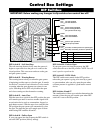
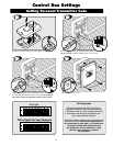
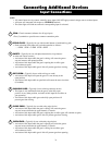
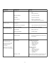
1 COM: Circuit common (reference for all logic input)
•Two(2)terminalstoprovideextracommonconnectionpoint.
2 CYCLE CLOSE: (Typically for use with doorbell button or hardwired key pad)
• Eachactivationatthisinputwillcycletheoperationasfollows:
….→ OPEN → STOP → CLOSE → STOP → OPEN → …
3 SAFETY: (Typically for use with photo beam device, loop detector
or other non-contact sensors)
• Activationofthisinputwhilethegateisclosingwillcausethegateto
stop and return to the opened position.
• Activationofthisinputwhilethegateisopeninghasnoeffect(gate
will continue to open).
• Activationofthisinputwhilegateisidlewillpreventgatefromclosing.
4 EXIT/OPEN: (Typically for use with exit loop or wand)
• Activationofthisinputwillopenthegateifit’snotalreadyatthe
open position
• Activationofthisinputwhileatopenlimitwillrestarttheautoclosetime
(if enabled).
5 SHADOW LOOP: (Typically for use with loop detector device)
• Thisinputisonlymonitoredwhenthegateisatthefullyopen
position. At any other position, activation of this input has no effect on
gate operation.
• Activationofthisinputwhilegateatthefullyopenpositionwill
prevent gate from closing.
6 CLOSE EDGE: (Typically for use with safety edge device)
• Activationofthisinputwhilethegateisclosingwillcausethegateto
stop and reverse direction for approximately 2 seconds.
• Activationofthisinputwhilethegateisopeninghasnoeffect(gatewillcontinuetoopen).
• Activationofthisinputwhilegateisidlewillpreventgatefromclosing.
7 OPEN EDGE: (Typically for use with safety edge device)
• Activationofthisinputwhilethegateisopeningwillcausethegateto
stop and reverse direction for approximately 2 seconds.
• Activationofthisinputwhilethegateisclosinghasnoeffect(gate
will continue to close).
• Activationofthisinputwhilegateisidlewillpreventgatefromopening.
1
2
3
4
7
5
6
MAX
MIN
P
I
H
E
R
S
P
A
I
N
ON
1 2 3 4 5 6 7
DIP
RECEIVER
SET
LIMIT
LEARN
TRANSMITTER
MODES
1 2 3 4 5 6 7
CYCLE
CLOSE
SAFETY
EXIT/
OPEN
SHADOW
LOOP
CLOSE
EDGE
OPEN
EDGE
BLKGRN RED
STALL FORCE
SWITCH
MASTER INPUTS
GRN WHT BLUE BRN ORG RED BLK
COM COM
18VAC SOLAR RELAY OUT
SLAVE INPUTS
GRN WHT
BLUE BRN ORG RED BLK
NC RLY-COM NO
+–~~
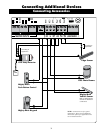
NOTE:
• Allcontrolinputsaredry-contact,normallyopen,inputs.DONOTapplyexternalvoltagesourcestotheseinputs.
• AllinputsareconnectedwithrespecttoCOMMON terminal.
• Thestatuslightwillblinkoncewhenitscorrespondinginputisactivated.
Input Connections
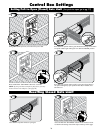
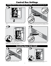
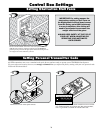
Connecting Additional Devices