


Technical Specifications
9
Mighty Mule® 500 E-Z Gate Opener
DRIVE
•Lowfrictionscrewdrive(linearactuator)ratedfor-5ºF
to+160ºF(-20ºCto+71ºC).Useofheaterbandsonarm
and control box will enhance performance in extreme cold
temperatures.
•Poweredbya12Vmotorwithintegralcasehardenedsteel
gear reducer. Motor speed reduced to 260 rpm. Generates
680 ft. lb. of torque at 12 V.
•Maximumopeningarcof110º.Approximateopeningtime
(90º):20seconds,dependingonweightofgate.
POWER
•Thesystemispoweredbya12Vdc,7.0Ah,sealed,
rechargeable acid battery.
•Batterychargeismaintainedbya120Vac,18Vacoutput
transformer rectified to 14.5 Vdc (40 VA) through the GTO
control board. Blade-style control board fuse is rated for
15 A.
NOTE: The transformer should not be directly
connected to any battery. Do not replace fuses with
higher ampere rated fuses; doing so will void your
warranty and may damage your control board.
•OPTIONAL:BatterychargeismaintainedbyGTOSolar
Panel Charger: float voltage of 14.5 Vdc output from a
10-7/8” x 10-1/2”solar panel. Generates minimum of 5 W
at 300 mA. A gated diode on the control board prevents
battery discharge.
CONTROL
•GTOmicroprocessor-basedcontrolboardissetforsingle
leaf, pull-to-open gate installations. DIP switches can be
adjusted to accommodate an optional kit for push-to-open
gates (see Accessory Catalog).
•Controlboardhastemperaturecompensatedcircuits.
•Acircuitonthecontrolboardregulatescharging.“Sleep
draw” is 40 mA; “active draw” is 2 to 5 A.
•Auto-memorizationofdigitaltransmittercode.
•GTOremote-mountedRFreceivertunedto318MHz.
•Operatorlengthwithpush-pulltubefullyretractedis
40-1/4” mounting point to mounting point. Max stroke 22”.
•Adjustableauto-closetimer(15to120s),andobstruction
sensitivity.
•Powerterminalblockaccommodatesatransformerorsolar
panels. NOTE: Do not use solar panel and transformer
at the same time.
•DIPswitchessimplifysetupofgateoperator.
•Accessoryterminalblockfullycompatiblewithpush
button controls, digital keypads, safety loops, etc.
•Controlboardallowsconnectionofsafetyedgesensors
and photoelectric sensors.
•Audioentrapmentalarmsoundsifunitencountersan
obstruction twice while opening or closing.
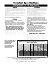
OPERATIONAL CAPACITY
•TheGateCapacityChartshowsapproximatecycles,per
day, you can expect from the Mighty Mule® 500 Automat-
ic Gate Operator when powered with a transformer. Actual
cycles may vary slightly depending upon the type and
condition of gate and installation.
Gate Weight
Gate Length
Number of Cycles* Per Day
Mighty Mule 500 Gate Capacity /Cycle Chart
Estimated number of daily cycles, based on use with a transformer and one(1) 12 Volt battery.
850 lbs.
750 lbs.
650 lbs.
550 lbs.
450 lbs.
350 lbs.
250 lbs.
150 lbs.
100 lbs.
50 lbs.
135
145
155
165
175
185
195
205
215
225
5’ - 6’
125
135
145
155
165
175
185
195
205
215
8’
125
135
145
155
165
175
185
195
205
10’
125
135
145
155
165
175
185
195
12’
125
135
145
155
165
175
185
14’
125
135
145
155
165
175
16’
NR
NR
NR
NR
NR
125
135
145
155
165
18’
NR
NR
NR
NR
NR
NR
NR
NR
NR
NR
NOTE: “NR” indicates this size
and weight combination is not
recommended for the
Mighty Mule® 500.
NOTE: Ball bearing hinges
should be used on all gates
weighing over 250 lb.
To determine the number of cycles the gate operator will perform using solar panels, please see the specifications
listed on page 23 or call (800) 543-1236 or (850) 575-4144 for more information.
* An operation cycle is one full opening and closing of the gate.
These specifications are subject to change without notice.