


20
MAX
MIN
P
I
H
E
R
S
P
A
I
N
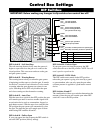
ON
1 2 3 4 5 6 7
DIP
RECEIVER
LEARN
TRANSMITTER
MODES
COM
CYCLE
CLOSE
SAFETY
EXIT/
OPEN
SHADOW
LOOP
CLOSE
EDGE
OPEN
EDGE
BLKGRN RED
STALL FORCE
SWITCH
MASTER INPUTS
GRN WHT BLUE BRN ORG RED BLK
COM
RELAY OUT
SLAVE INPUTS
GRN WHT BLUE BRN ORG RED BLK
NO
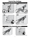
MASTER INPUTS
GRN WHT BLUE BRN ORG RED BLK
7
COM
CYCLE
CLOSE
SAFETY
SWITCH
COM
MASTER INPUTS
GRN WHT BLUE BRN ORG RED BLK
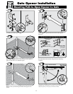
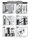
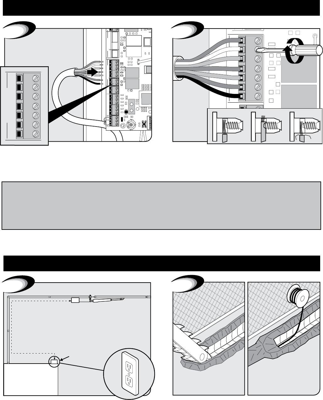
Correct
Wrong Wrong
8
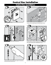
Secure wires in terminals.Insert 7 wires into corresponding color terminals.
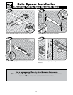
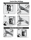
CAUTION: Please
call your power company
before you dig. Failure to
do so could cause injury
or even death.
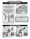
10
Top View
Min 3 Ft
Max 1,000 Ft
GTO Transformer
Mounts Here
9
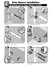
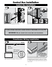
Locate power outlet and identify wire path to control box.
NOTE: If OUTLET is OUTSIDE use weatherproof cover.
Dig trench and lay wire from AC power source to control box.
Use only 16 guage multi-stranded, low voltage, PVC sheathed
wire (RB509). NOTE: DO NOT use telephone wire or solid core
wire. NEVER splice wires together. We recommend running wire
in PVC conduit.
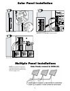
Transformer Wiring Installation
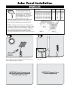
If u s I n g o p t I o n a l s o l a r p a n e l c h a r g e r I n s t e a d o f t r a n s f o r m e r , g o t o p a g e 23.
Important: do n o t c o n n e c t b o t h s o l a r p a n e l a n d t r a n s f o r m e r .
Control Box Installation
Control Box Installation