


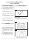
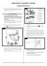
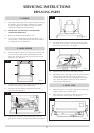
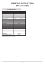


3.3 Remove the lint arrestor by folding the tabs back. See
diagram 6.
3.4 Undo the compression nut on the pilot unit, disconnect the
ignition lead from the electrode by pulling gently down on
the wire. Undo the two screws and the pilot unit can be
removed. See diagram 7
3.5 Reassemble in reverse order, check for gas leaks.
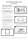
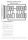
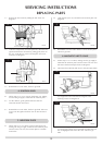
4.1 Follow steps 2.1 to 2.5 to remove the burner unit, making
sure that the gas supply is isolated at the isolation point.
4.2 Cut the cable tie, gently pull the lead out from the
electrode and the control unit.
4.3 Reassemble in reverse order, check for gas leaks. Take care
not to route the ignition lead too close to other electrical
leads.
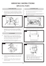
5.1 Follow steps 2.1 to 2.5 above to remove the burner unit,
making sure the gas supply is isolated at the isolation point.
Turn the burner unit over, the aeration plate is accessible
from below.
5.2 Undo the M5 nyloc nut, and remove the aeration plate. See
diagram 8
5.3 Reassemble in reverse order with the correct aeration plate.
Check for gas leaks.
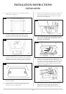
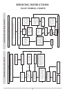
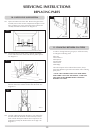
6.1 Follow steps 2.1 to 2.5 above, making sure the gas supply is
isolated at the isolation point. Turn the burner unit over and
disconnect the thermocouple lead. See diagram 9
6.2 Disconnect the TTB leads and unscrew the interrupter block
(A). Support the valve and undo the magnetic valve
retaining nut (B). See diagram 10
6.3 Remove the magnetic valve unit located inside. Reassemble
in reverse order, taking care to assemble the TTB leads with
the red highlighted one closest the valve. Check for gas
leaks.
6. MAGNETIC SAFETY VALVE
5. AERATION PLATE
4. IGNITION LEAD
18
SERVICING INSTRUCTIONS
REPLACING PARTS
7
8
9
10
AR1445
AR1448
AR1459
AR1458
B
A
6
AR1444