


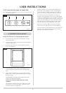
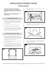
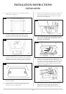
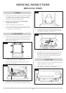

2.6 Remove the four black screws in the firebox and lift the
firebox clear. See diagram 5.
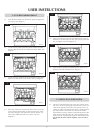
2.7 For Midi and Highline versions of the F40, it will be
necessary to remove the base panel. This lifts up and
through the upper part of the carcass. See diagram 6.
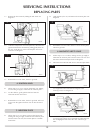
2.8 It will now be possible to access the two tabs for bolting the
appliance down (if required). Position the stove ensuring all
appropriate clearances are observed. Using a pencil mark
the position of the holes in the fixing bracket. See diagram
7.
2.9 Remove the stove and drill the holes using a masonary drill.
Insert the rawlplugs.
2.10 Reposition the stove and level it using the three levelling
bolts in the base. Screw the stove down. Replace the
decorative base cover panel if fitted.
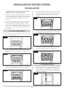
2.11 Refit the fire box and burner unit to the stove taking care to
reconnect the small TTB electrical connector to the left
hand terminal and the large TTB connector to the right
hand terminal. See diagram 8.
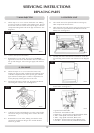
2.12 THE TTB CONNECTIONS IN THE INTERUPTOR BLOCK
MUST HAVE THE RED HIGHLIGHTED SPADE CLOSEST
THE VALVE. SEE DIAGRAM 9.
2.13 Having run the gas supply to the stove, PURGE THE
SUPPLY, this is essential to expel any debris that may block
the controls. Connect the gas supply to the 8mm test point
located at the lower right hand side of the stove. A gas
soundness check must be completed up to the gas inlet
connection. See diagram 10.
2.14 Check the pull of the flue system by applying a lighted
smoke pellet to the flue system opening. If there is a
definite flow into the chimney, proceed with the
installation, if not warm the chimney for a few minutes.
12
INSTALLATION INSTRUCTIONS
INSTALLATION
8
9
AR1472
AR1362
7
AR1456
6
AR1471
5
AR1470
10
AR1461