


1.1 All principle components can be replaced without removing
the appliance from its installation, although it is essential
that the gas supply to the appliance is turned off at the
isolation device before proceeding further.
1.2 ENSURE THAT THE APPLIANCE IS COLD BEFORE
COMENCING WORK ON IT.
1.3 Remove the batteries from the battery box.
1.4 If access to the components is restricted the burner and
control system is a self contained unit and can be removed
as a single unit for easy maintenance.
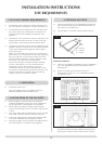
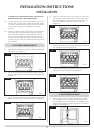
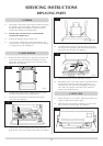
2.1 Remove the door from the stove, open the lower door, and
remove the lower panel. Remove the batteries from the
battery box, undo the six pozidriv screws and remove the
glass frame. See diagram 1
2.2 Carefully remove the ceramic components from the stove
and store safely. Remove the touchpad panel
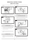
2.3 Disconnect the TTB and the touchpad leads from the
control unit. See diagram 2
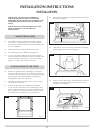
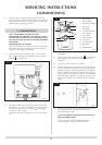
2.4 Undo the gas connection at the pressure test point, and
undo the two screws at the back of the firebox. See diagram
3
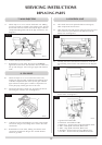
2.5 Carefully pull the burner unit forward until access to the
rear of the valve is possible. Undo the thermocouple lead
and remove the TTB wires. See diagram 4
2.5 The burner unit can now be removed to work on.
2.6 Reassemble in the reverse order, check for gas leaks. When
connecting the TTB wires in the back of the valve, it is
essential for the wire with the red highlight be closest the
valve. Note also, that the connectors for the TTB in the
control unit are different sizes.
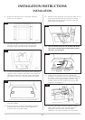
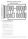
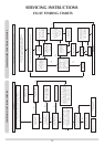
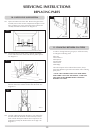
3.1 Follow the steps 2.1 to 2.5 above, making sure that the gas
supply is isolated at the isolation point.
3.2 With the burner unit removed, undo the two screws and
remove the front aeration guide. See diagram 5
3. PILOT UNIT
2. MAIN BURNER
1. GENERAL
17
SERVICING INSTRUCTIONS
REPLACING PARTS
1
2
3
4
5
AR1454
AR1463
AR1457
AR1462
AR1443