


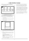
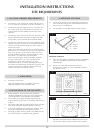
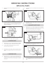

4.2 Close the door by pushing the lower right corner of the
door until a click is heard. The door will now have latched.
Opening is done by the lower right hand door, again until a
click is heard, and opening to its stop.
NOTE: THE HANDSET HAS BEEN FACTORY
PROGRAMMED TO OPERATE THIS APPLIANCE. IF THE
HANDSET OR CONTROL UNIT HAS BEEN REPLACED, IT
WILL BE NECESSARY TO FOLLOW THE PROGRAMMING
PROCEDURE.
PROGRAMMING THE HANDSET
Section 5 must be read in total before trying to programme
the handset! The sequence must be performed while the
ON/OFF on the display is still flashing.
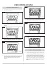
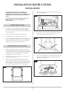
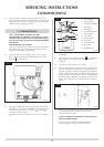
5.1 Open the lower door by pressing until a ‘click’ is heard.
Now switch the button on the control unit to the Unlock
position . See diagram 18.
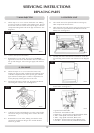
5.2 The remote handset must now be programmed. Push the ON /
OFF button (11), the ON or OFF display will start flashing. Then
press the ON / OFF button (11), and the
( )
(10) and
( )
(13) buttons at the same time.
Immediately after press the SET button (12) once. See diagram
19.
5.3 The clock (7) will appear on the display. After a few seconds this
will disappear.
5.4 Finally push the switch to the Lock position , towards the rear
of the appliance. The remote should now be tuned to the
control box.
5.5 Close the lower door untill a ‘click’ is heard.
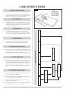
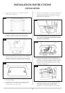
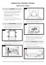
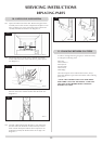
5.6 Close all openable doors and windows in the room, ignite the
appliance and operate on maximum for 10 minutes. Remove
the plastic sight plug from the right hand side of the appliance.
Position a lighted smoke match just inside the draught diverter
opening and check that all smoke is drawn into the opening by
viewing through the sight hole. See diagram 20. If there is any
doubt, run the appliance for a further 10 minutes, and repeat
the test.
5.7 If there are any extractor fans in adjacent rooms, the test must
be repeated with the fans running on maximum and
interconnecting doors open.
IF SPILLAGE PERSISTS, DISCONNECT THE APPLIANCE
AND SEEK EXPERT ADVICE.
For future reference record the installation details on
commissionging sheet page 3 of these instructions.
5. COMMISSIONING
14
SERVICING INSTRUCTIONS
COMMISSIONING
18
20
AR1493
19
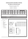
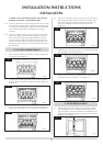
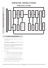
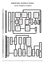
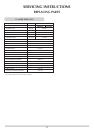
1: Flame display
2: Celsius display
3: Temperature display
4: On display
5: Off display
6: Low battery display
7: Clock display
8: Auto display
9: Manual display
10: UP button
11: ON/OFF button
12: SET button
13: DOWN button
AR1665
1
2
3
10
11
5
6
7
4
8
9
12
13
AR1676