


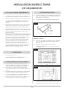
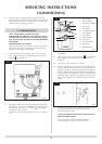
1.1 The chimney or flue system must comply with the rules in
force, and must be a minimum of 127mm in diameter. (5").
1.2 The minimum effective height of the flue or chimney must
be 3 metres (10ft). Any horizontal flue run from the rear
outlet should not exceed 100mm from the back of the
appliance.
1.3 The chimney or flue must be free from any obstruction. Any
damper plates should be removed or secured in the fully
open position, and no restrictor plates should be fitted.
1.4 The chimney should be swept prior to the installation of the
appliance. However, where it can be seen that the chimney
is clean and unobstructed throughout its entire length, it
need not be swept.
NOTE: If it is intended to fit the stove into a existing brick
built chimney a 5" (127mm) liner must be used. Larger lined
flues may work, but in some instances could cause cold
start flue problems resulting in nuisance shutdown. Lined
flues above 7" (175mm) are not recommended.
Due to recent changes to European chimney standards,
new flue’s and chimney’s are now described by their
temperature, pressure and resistance to corrosion,
condensation and fire. To assist in identifying the correct
flue system, the minimum flue specification is shown in the
technical specification on page 8 of this book. Existing
chimney’s are not covered by this system.
2.1 Consult the rules in force.
Note: This appliance does not normally require any
additional ventilation when installed in G.B.
3.1 Before installation, ensure that the local distribution
conditions (identification of the type of gas and pressure)
and the adjustment of the appliance are compatible.
3.2 Ensure that the gas supply is capable of delivering the
required amount of gas, and is in accordance with the rules
in force.
3.3 Soft copper tubing and soft soldered joints can be used but
must not be closer than 50mm to the base of the tray.
3.4 A means of isolating the gas supply to the appliance must
be provided independent of any appliance control.
3.5 All supply gas pipes must be purged of any debris that may
have entered, prior to connection to the appliance.
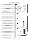
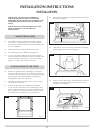
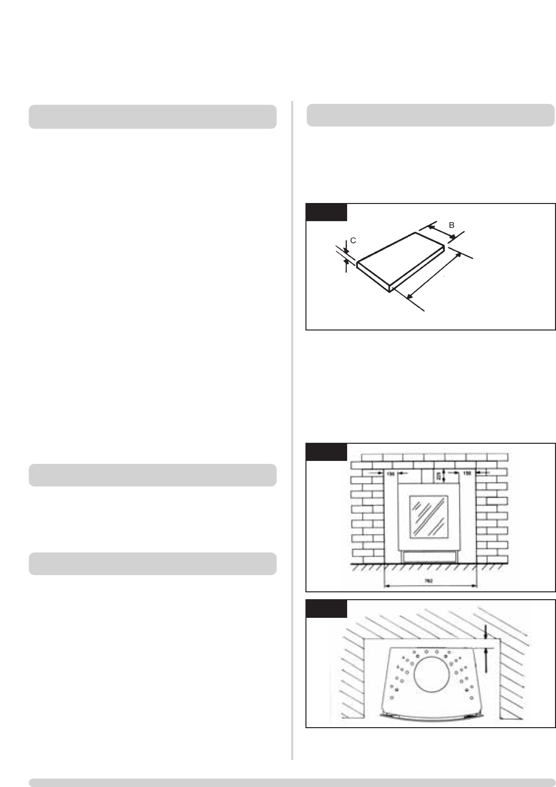
4.1 This fire must stand on a non-combustible hearth that is at
least 12mm thick and projects 50mm minimum from the
base of the fire in all directions.
4.2 Do not install in a room that contains a bath or shower.
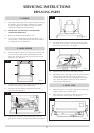
MINIMUM CLEARANCE
4.3 The fire is not suitable for installation against a combustible
wall. All combustible materials must be removed from
behind the fire.
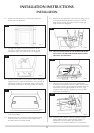
4.4 Ensure you comply with all minimum clearance
measurements, whether or not to combustible materials.
See diagram 2 & 2A.
The above dimensions provide adequate clearance at the
side and rear of the fire so that controls can be reached.
4. APPLIANCE LOCATION
3. INSTALLATION OF THE GAS SUPPY
2. VENTILATION
1. FLUE AND CHIMNEY REQUIREMENTS
10
INSTALLATION INSTRUCTIONS
SITE REQUIREMENTS
1
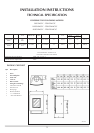
A = 562mm
B = 431mm
C = 12mm
AR1468
AR1469
50
2
3