


Wiring and Connections
15 Liebert
®
AC4
™
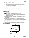
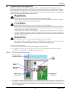
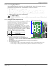
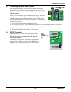
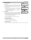
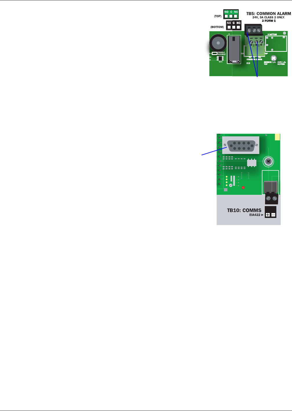
3.3 Connecting Common Alarm Outputs
The common alarm relay, found in the top right corner of the
Liebert AC4, permits the user to connect auxiliary notification
equipment, such as lights, horns and sirens, to the Liebert AC4.
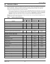
To determine the proper wire size, see Table 4 Wiring
specifications.
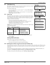
There are two connectors for the common alarm output. However,
the connectors are not individual relay outputs. The connectors
should be treated as a double-pole, double-throw (DPDT) relay.
The common alarm relay is energized whenever an alarm occurs.
To connect an output:
1. Turn OFF electrical power to the Liebert AC4.
2. If necessary, remove a conduit knockout to permit wire entry into the Liebert AC4 enclosure.
3. Bring the wire(s) into the Liebert AC4 enclosure through a conduit knockout or access slot.
4. Loosen the appropriate screw and slip the stripped end of the wire into the terminal block.
5. Tighten the screw until it holds the wire snugly.
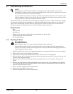
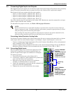
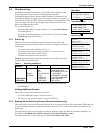
3.4 RS232 Connector
The Liebert AC4’s Service Terminal Interface offers
full configuration and monitoring capability via the
RS232 port (see A.2 - Connecting to the Service
Terminal Interface).
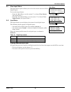
The RS232 port requires a null modem cable. Connect
one end of the cable to the Liebert AC4’s RS232 port,
shown at right, and the other end to the COM1 port of
a laptop computer or video terminal.
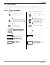
Common alarm outputs
Serial
interface
connector
(RS232/EIA5
74)