


Introduction
5Liebert
®
AC4
™
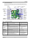
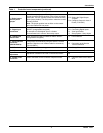
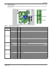
I - Digital output
loss-of-power
jumper
One of four output jumpers. Each digital output has a
jumper to set the fail-safe position of the output point when
power fails. The OFF position makes the contact Normally
Open (factory default). The ON position makes the contact
Normally Closed.
Note: The jumper position has no effect on the contact
when the Liebert AC4 has power.
3.2.3: Setting the Digital Output
Jumpers
7.6.4: Configure Output for Loss of
Power (“Fail-Safe”)
J - Digital input
connectors
Each of the four input connections is a two-state point:
ON/OFF (energized/de-energized).
An example of a field digital input is a Liebert
Environmental unit’s common alarm relay output.
3.0: Wiring and Connections
3.2.1: Connecting Digital Inputs
5.4: View Input Status
7.3: Setup System - Setup Inputs
K - Digital input
status LEDs
Each input has an LED to indicate its status: ON/OFF
(energized/de-energized).
1.7: LED Indicators
L - Serial interface
connector
(RS232/EIA574)
Connection for laptop or video terminal. Used for
configuration and monitoring using the Service Terminal
Interface. Requires a null modem cable for connectivity
(P/N 201258P1).
3.4: RS232 Connector
A.2: Connecting to the Service
Terminal Interface
M - DIP switch 1 DIP switch used for resetting password to default. 7.7.1: Change Password
N - LCD connector Connection for the LCD on the enclosure door. N/A
O - LCD contrast
adjustment
Adjustment contrast for the LCD on the enclosure door. N/A
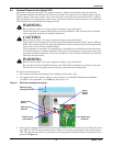
P - 24VAC power
connector
Power connection for the controller. Requires 24VAC.
2.4: Connect Power to the Liebert
AC4
Table 1 Controller board components (continued)
Item Description For more information, see: