


60
MODEL 54eA SECTION 9.0
CALIBRATION - TOTAL CHLORINE
SECTION 9.0
CALIBRATION - TOTAL CHLORINE
9.1 INTRODUCTION
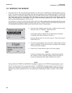
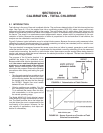
Total chlorine is the sum of free and combined chlorine. The continuous determination of total chlorine requires two
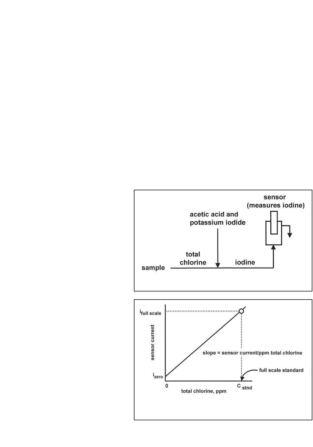
steps. See Figure 9-1. First, the sample flows into a conditioning system (SCS 921) where a pump continuously
adds acetic acid and potassium iodide to the sample. The acid lowers the pH, which allows total chlorine in the
sample to quantitatively oxidize the iodide in the reagent to iodine. In the second step, the treated sample flows to
the sensor. The sensor is a membrane-covered amperometric sensor, whose output is proportional to the con-
centration of iodine. Because the concentration of iodine is proportional to the concentration of total chlorine, the
analyzer can be calibrated to read total chlorine.
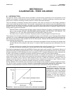
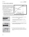
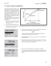
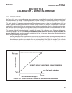
Figure 9-2 shows a typical calibration curve for a total chlorine sensor. Because the sensor really measures iodine,
calibrating the sensor requires exposing it to a solution containing no iodine (zero standard) and to a solution con-
taining a known amount of iodine (full-scale standard).
The zero standard is necessary because the sensor, even when no iodine is present, generates a small current
called the residual current. The analyzer compensates for the residual current by subtracting it from the measured
current before converting the result to a total chlorine value. New sensors require zeroing before being placed in
service, and sensors should be zeroed whenever the electrolyte solution is replaced. The best zero standard is
sample without reagent added.
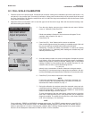
The purpose of the full-scale standard is to
establish the slope of the calibration curve.
Because stable total chlorine standards do not
exist, the sensor must be calibrated against
a test run on a grab sample of the process
liquid. Several manufacturers offer portable
test kits for this purpose. Observe the following
precautions when taking and testing the grab
sample.
• Take the grab sample from a point as close
as possible to the inlet of the SCS921 sam-
ple conditioning system. Be sure that taking
the sample does not alter the flow through
the SCS921. Sample flow must remain
between 80 and 100 mL/min.
• Chlorine solutions are unstable. Run the
test immediately after taking the sample.
Try to calibrate the sensor when the chlo-
rine concentration is at the upper end of
the normal operating range.
The Model 499ACL-02 (total chlorine) sensor
loses sensitivity at high concentrations of chlo-
rine. The 54eA controller has a dual slope fea-
ture that allows the user to compensate for the
non-linearity of the sensor. However, for the
vast majority of applications, dual slope cali-
bration is unnecessary.
FIGURE 9-1. Determination of Total Chlorine
FIGURE 9-2. Sensor Current as a Function of Total
Chlorine Concentration