MODEL 54eA SECTION 15.0
TROUBLESHOOTING
15.14 SIMULATING TEMPERATURE
15.14.1 General.
The 54eA controller accepts either a Pt100 RTD (for pH,
499ADO, 499ATrDO, 499ACL-01, 499ACL-02, 499ACL-03,
and 499AOZ sensors) or a 22k NTC thermistor (for Hx438
and Gx448 DO sensors and most steam-sterilizable DO
sensors from other manufacturers). The Pt100 RTD is in a
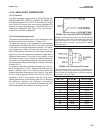
three-wire configuration. See Figure 15-4. The 22k ther-
mistor has a two-wire configuration.
15.14.2 Simulating temperature
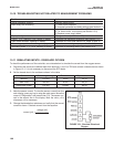
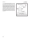
To simulate the temperature input, wire a decade box to the
analyzer or junction box as shown in Figure 15-5.
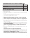
To check the accuracy of the temperature measurement,
set the resistor simulating the RTD to the values indicated
in the table and note the temperature readings. The meas-
ured temperature might not agree with the value in the
table. During sensor calibration an offset might have been
applied to make the measured temperature agree with a
standard thermometer. The offset is also applied to the
simulated resistance. The controller is measuring tempera-
ture correctly if the difference between measured tempera-
tures equals the difference between the values in the table
to within ±0.1°C.
For example, start with a simulated resistance of 103.9 Ω,
which corresponds to 10.0°C. Assume the offset from the
sensor calibration was -0.3 Ω. Because of the offset, the
analyzer calculates temperature using 103.6 Ω. The result
is 9.2°C. Now change the resistance to 107.8 Ω, which cor-
responds to 20.0°C. The analyzer uses 107.5 Ω to calcu-
late the temperature, so the display reads 19.2°C. Because
the difference between the displayed temperatures
(10.0°C) is the same as the difference between the simu-
lated temperatures, the analyzer is working correctly.
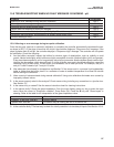
Temp. (°C) Pt 100 (
ΩΩ
) 22k NTC (k
ΩΩ
)
0 100.0 64.88
10 103.9 41.33
20 107.8 26.99
25 109.7 22.00
30 111.7 18.03
40 115.5 12.31
50 119.4 8.565
60 123.2 6.072
70 127.1 4.378
80 130.9 3.208
85 132.8 2.761
90 134.7 2.385
100 138.5 1.798
FIGURE 15-4. Three-Wire RTD Configuration.
Although only two wires are required to connect the RTD
to the analyzer, using a third (and sometimes fourth) wire
allows the analyzer to correct for the resistance of the
lead wires and for changes in the lead wire resistance
with temperature.
FIGURE 15-5. Simulating RTD Inputs.
The figure shows wiring connections for sensors con-
taining a Pt 100 RTD. For sensors using a 22k NTC ther-
mistor (Hx438 and Gx448 sensors), wire the decade box
to terminals 1 and 3 on TB6.
103


