


Rosemount Tank Radar REX
Chapter 10 Mechanical Installation
10-4
Installation Manual
308014EN, Edition 4
May 2013
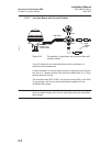
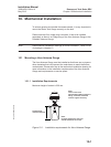
10.1.4 Installation on the tank
Follow this Step by Step instruction when installing the Cone Antenna
Gauge.
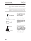
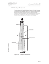
Note! When determining the dimensions for conduits (if used), note that the
Horn Antenna Gauge may be inclined 4° towards the center of the tank.
See Figure 10-2. Use flexible conduits close to the Radar Tank Gauge.
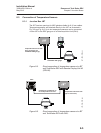
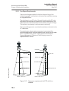
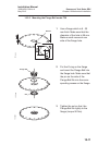
1 Check that all parts and tools
are available before carrying
them up to the tank top.
2 Carefully insert the horn and
flange assembly into the socket.
Tighten the flange onto the
socket by using customer sup-
plied screws and nuts. Check
that the socket height is less
than 330 mm.
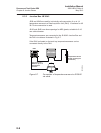
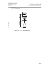
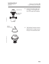
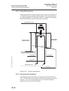
3 Mount the Waveguide Unit into
the base of the Transmitter
Head. On one end of the Wave-
guide Unit there are two screws
with washers fitted. Mount the
Waveguide Unit with this end
first into the base of the Trans-
mitter Head. Enter the stop
screws and tighten them.
Horn and flange assembly
Gasket (Customer supplied)
Customer supplied
flange
Cone_pict1.eps
Socket
W11W12
FOR
INTRINSICALLY
SAFE CIRCUITS
ONLY
"i"
Waveguide unit
M6 stop screw
Transmitter head
Cone_pict2.eps