11-3
Rosemount Tank Radar REX
Chapter 11 Electrical Installation of the
Installation Manual
308014EN, Edition 4
May 2013
11.2 Cabling for TRL/2 Bus
The TRL/2 Bus requires a twisted and shielded pair with an area of min
0.50 mm
2
(AWG 20 or similar). The maximum length of the TRL/2 Bus is
approximately 4 km. The TRL/2 Bus can normally use existing cables in
the tank area.
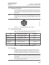
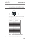
Note! Wherever two or more TRL/2 Buses run alongside each other, sharing
the same cable or conduit tube, use twisted and shielded wire and make
sure that each pair of bus wires is individually shielded in order to avoid
crosstalk.
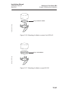
Figure 11-1. Individually shielded pairs of cables.
11.3 Recommended Cables
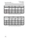
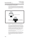
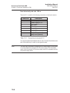
Table 11-3 shows typical cable types that can be used for connecting the
REX gauge. Other cables of similar type may also be used.
Table 11-3. Example of applicable cable standards.
11.4 Grounding
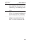
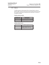
According to national code of practice the Transmitter Head or Data
Acquisition Unit can be grounded by connecting an exterior 4 mm
2
wire
to a potential equalization network, or, if no such exists, to the tank
structure. A grounding lug is available on the enclosure for this purpose.
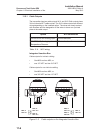
Note! When the enclosure is connected to a potential equalizing network or to
the tank structure, the protective ground with the power supply must not
be connected.
If the enclosure is not externally grounded, the protective ground with the
power supply should be connected.
Type Manufacturing standard Core Size
Signal BS 5308 part 1, type 1
1 mm
2
Signal (armoured) BS 5308 part 2, type 1
1 mm
2
Power (armoured) BS 5467
1.5 mm
2
Power (unar-
moured)
IEC 228, IEC 227
1.5 mm
2
Intrinsically safe IEC 228, IEC 227
0.5 mm
2
Cables_shield.eps


